6. 外设
6.1 GPIO
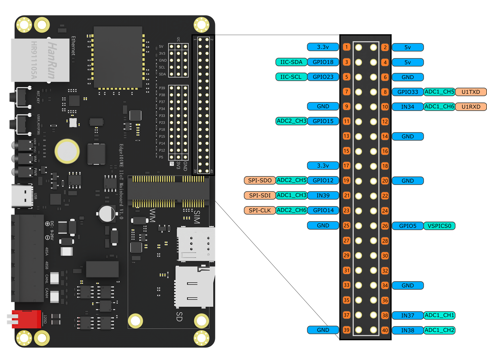
Edge101WE主板上的40PIN扩展接口引出了11个GPIO,同时在主板上也引出了 Gravity 3PIN接口用于直接连接DFRobot众多的Gravity接口设备。GPIO 都可以被配置为内部上拉/下拉,或者被设置为高阻。当被配置为输入时,可通过读取寄存器获取输入值。输入管脚也可以被设置为通过边缘触发或电平触发来产生 CPU 中断。IO 管脚都是双向、非反相和三态的,包括带有三态控制的输入和输出缓冲器。这些管脚可以复用作其他功能,例如SDIO、UART、SPI 等。
40PIN扩展接口图
Gravity扩展接口示意图

40P IN接口号 |
引脚名称 |
GPIO功能 |
ADC功能 |
通信功能 |
复用功能 |
|---|---|---|---|---|---|
3 |
GPI O18:raw- latex:`I`2C-SDA |
GPIO18 可作为输 入和输出 |
I2C-SDA |
Gravity I2C-SDA |
|
5 |
GPI O23:raw- latex:`I`2C-SCL |
GPIO23 可作为输 入和输出 |
I2C-SCL |
Gravity I2C-SCL |
|
8 |
GPIO33:r aw-latex :ADC1 _CH5:ra w-latex: U1TXD |
GPIO33 可作为输 入和输出 |
U1TXD |
PCIe插 槽U1TXD |
|
10 |
IN34:r aw-latex :ADC1 _CH6:ra w-latex: U1RXD |
GP IO34只能 作为输入 |
U1RXD |
PCIe插 槽U1RXD |
|
11 |
GPIO1 5:raw-la tex:AD C2_CH3 |
GPIO15 可作为输 入和输出 |
ADC2_CH3 |
板载LED |
|
19 |
GP IO12:raw -latex:` ADC2`_ CH5:raw- latex:SPI-SDO |
GPIO12 可作为输 入和输出 |
ADC2_CH5 |
SPI-SDO |
Gravity SPI-SDO |
21 |
IN39:raw -latex:` ADC1`_ CH3:raw- latex:SPI-SDI |
GP IO39只能 作为输入 |
ADC1_CH3 |
SPI-SDI |
Gravity SPI-SDI |
23 |
GP IO14:raw -latex:` ADC2`_ CH6:raw- latex:SPI-CLK |
GPIO14 可作为输 入和输出 |
ADC2_CH6 |
SPI-CLK |
Gravity SPI-CLK |
26 |
GP IO5:raw- latex:VSPICS0 |
GPIO5 可作为输 入和输出 |
SPICS0 |
Gravity SPICS0 |
|
38 |
IN3 7:raw-la tex:AD C1_CH1 |
GP IO37只能 作为输入 |
ADC1_CH1 |
||
40 |
IN3 8:raw-la tex:AD C1_CH2 |
GP IO38只能 作为输入 |
ADC1_CH2 |
板载按钮 |
注意:GPIO34 ~ GPIO38只能用于输入,而且PULLUP 和 PULLDOWN模式都不具备。 在模拟输入时,你必须使用连接到 ADC 的 GPIO。但是,如果你使用无线网络,比如 WiFi,你将无法使用 ADC 2。
6.1.1 GPIO输出
API参考
pinMode() - 设置GPIO口工作模式
使用pinMode(pin, mode)来设置GPIO口工作模式,mode可选项为:OUTPUT、INPUT、INPUT_PULLUP、INPUT_PULLDOWN模式(输出、输入、上拉输入、下拉输入,另外还有开漏等模式),内部上拉和下拉的阻值为45K 。(SPECIAL、FUNCTION_ 1到6、ANALOG未验证)
语法
pinMode(pin, mode)
参数
传 入 值 |
说明 |
值范围 |
|---|---|---|
p in |
GPIO 端口号 |
0 ~ 39 |
mo de |
GP IO模式 |
OUTPUT、INPUT、INPUT_PULLU P、INPUT_PULLDOWN、PULLUP、PULLDOWN、OUTPUT_OPEN_DRAI N、OPEN_DRAIN、ANALOG(输出、输入、输入上拉、输入下拉 、输出上拉、输出下拉、输出开漏、输入开漏、模拟输入) |
返回
无
digitalWrite() - 设置输出状态
使用digitalWrite(pin, value)来设置输出状态,value可选值为HIGH或LOW,即1和0。
语法
digitalWrite(pin, value)
参数
传入值 |
说明 |
值范围 |
|---|---|---|
pin |
GPIO端口号 |
0 ~ 39 |
value |
输出电平 |
HIGH或LOW,即1和0 |
返回
无
例程:板载绿色用户LED灯闪烁的Blink例程
(参考Arduino IDE例程 Examples -> Basics -> Blink)
#define userLED 15 //定义板载LED为GPIO15

// 当您按下复位或接通电路板电源时,setup函数运行一次
void setup() {
  // 初始化数字口 USER_LED 为输出,主板上的用户LED为GPIO15
  pinMode(userLED, OUTPUT);
}

// loop函数永远反复运行
void loop() {
  digitalWrite(userLED, HIGH);   // 关闭LED (高电平)
  delay(1000);                    // 等待1秒
  digitalWrite(userLED, LOW);    // 点亮LED
  delay(1000);                    // 等待1秒
}
6.1.2 GPIO输入
API参考
digitalRead() - 读取GPIO口电平
语法
digitalRead(pin)
参数
传入值 |
说明 |
值范围 |
|---|---|---|
pin |
GPIO端口号 |
0 ~ 39 |
返回
返回值 |
说明 |
值范围 |
|---|---|---|
bool |
GPIO端口电平状态 |
HIGH或LOW,即1和0 |
例程:按钮输入
将连接板载按钮的GPIO38设置为输入,连接板载LED的GPIO15设置为输出,当按钮按下时LED灯亮。
参考Arduino IDE例程 Examples -> Digital -> Button
// 使用不会改变的常数来定义pin的序号
const int buttonPin = 38;   // 板载按钮的GPIO38
const int ledPin =  15;      // 板载LED的GPIO15

// 变量将更改
int buttonState = 0;        // 使用一个变量来保存按钮状态

void setup() {
  // 初始化LED pin为输出:
  pinMode(ledPin, OUTPUT);
  // 初始化button pin为输入
  pinMode(buttonPin, INPUT);
}

void loop() {
  // 读取按钮状态
  buttonState = digitalRead(buttonPin);

  // 如果按钮输入为低电平代表按钮按下,点亮主板上绿色用户LED
  if (buttonState == LOW) {
    // 点亮LED
    digitalWrite(ledPin, LOW);
  } else {
    // 关闭LED
    digitalWrite(ledPin, HIGH);
  }
}
如果外部电路没有设计上拉或下拉电阻,当GPIO作为输入时需要将内部上拉或下拉电阻使能,以便准确识别电平信号。
// 初始化button pin为输入,不上拉也不下拉
  pinMode(buttonPin, INPUT);

// 初始化button pin为输入,并且上拉使能
  pinMode(buttonPin, INPUT_PULLUP);

// 初始化button pin为输入,并且下拉使能
  pinMode(buttonPin, INPUT_PULLDOWN);
注意:以下GPIO已经在内部具有上下拉功能 GPIO0:内部上拉 GPIO5:内部上拉 GPIO12:内部下拉
GPIO12上电时的电平会决定FLASH存储器的工作电压,上电时该脚为高则认为FLASH工作于1.8V,为低则认为FLASH工作于3.3V。
注意:GPIO12内部已下拉,即FLASH是工作于3.3V的,若外部电路接强上拉则可能导致主板工作异常。
6.1.3 输入中断
API参考
attachInterrupt() - 置外部中断
使用attachInterrupt(uint8_t pin, void (*)(void), int mode) 或 attachInterruptArg(uint8_t pin, void (*)(void), void arg, int mode)来设置外部中断。
语法
attachInterrupt(uint8_t pin, void (*)(void), int mode)
attachInterruptArg(uint8_t pin, void (*)(void*), void * arg, int mode)
参数
传入值 |
说明 |
值范围 |
|---|---|---|
uint8_t pin |
GPIO端口号 |
0 ~ 39 |
void (*)(void) |
中断触发时的回调函数 |
|
void * arg |
回调函数输入参数 |
|
int mode |
外部中断触发模式 |
RISING、FALL ING、CHANGE、ONLOW、ONH IGH(上升沿、下降沿、改 变时、低电平、高电平) |
返回
无
detachInterrupt() - 关闭外部中断
语法
detachInterrupt(uint8_t pin)
参数
传入值 |
说明 |
值范围 |
|---|---|---|
uint8_t pin |
GPIO端口号 |
0 ~ 39 |
返回
无
例程:GPIO电平变化中断测试例程
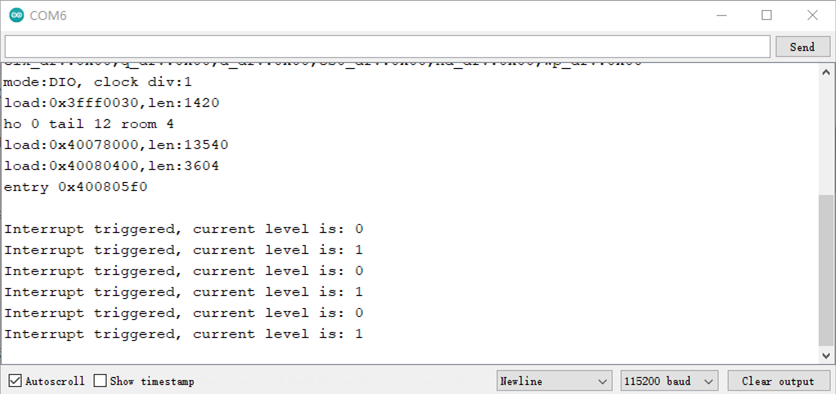
当按钮按下时产生一次中断,按钮释放时又产生一次中断,每次中断打印出当前GPIO38的电平状态。当按钮电平状态改变大于5次关闭此GPIO38的中断。
为了在长时间的高速缓存禁用操作(例如SPI Flash写,OTA更新等)中保持程序的功能,需要将ISR(中断服务例程)放入IRAM中,以便在禁用高速缓存的同时ISR仍可以运行。
(IRAM_ATTR相关介绍 https://docs.espressif.com/projects/esp-idf/zh_CN/latest/esp32/api-guides/general-notes.html)
#define userButton 38 //定义板载按钮为GPIO38

volatile bool pressed = false;  //按钮按下标志
volatile int pressCounter = 0; //按钮电平变化计数器

// IRAM_ATTR定义callBack中断服务函数在IRAM(指令RAM)中运行,以便在SPI Flash写、OTA更新等禁用高速缓存的同时ISR仍可以运行。
void IRAM_ATTR callBack(void)
{
  pressed = true;
  pressCounter ++;
}

void setup()
{
  Serial.begin(115200);
  Serial.println();
  pinMode(userButton, INPUT_PULLUP);
  attachInterrupt(userButton, callBack, CHANGE); //使能中断
}
void loop()
{
  if(pressed == true) {
    pressed = false;
    int level = digitalRead(userButton); //读取加载到userButton上的电平
    Serial.printf("Interrupt triggered, current level is: %d\n", level);
  }
  // 如果按钮状态变化大于5次,关闭这个外部中断口
  if (pressCounter > 5) {
    detachInterrupt(userButton); //失能中断
  }
}
打印结果:
例程:GPIO中断例程
(参考Arduino IDE例程 Examples -> Examples for Edge101WE -> ESP32/GPIO/GPIOInterrupt)
连接在GPIO38、GPIO39的两个按钮用于产生输入中断,当按钮按下串口打印出结果,程序会10秒钟后关闭button1中断,此时button1将不能使用。
#include <Arduino.h>
// 定义结构体
struct Button {
    const uint8_t PIN;
    uint32_t numberKeyPresses;
    bool pressed;
};
// 初始化结构体
Button button1 = {38, 0, false};
Button button2 = {39, 0, false};
// 运行在IRAM的中断服务函数
void IRAM_ATTR isr(void* arg) {
    Button* s = static_cast<Button*>(arg);
    s->numberKeyPresses += 1;
    s->pressed = true;
}

void IRAM_ATTR isr() {
    button2.numberKeyPresses += 1;
    button2.pressed = true;
}

void setup() {
    Serial.begin(115200);
    pinMode(button1.PIN, INPUT_PULLUP);
    attachInterruptArg(button1.PIN, isr, &button1, FALLING);
    pinMode(button2.PIN, INPUT_PULLUP);
    attachInterrupt(button2.PIN, isr, FALLING);
}

void loop() {
    if (button1.pressed) {
        Serial.printf("Button 1 has been pressed %u times\n", button1.numberKeyPresses);
        button1.pressed = false;
    }
    if (button2.pressed) {
        Serial.printf("Button 2 has been pressed %u times\n", button2.numberKeyPresses);
        button2.pressed = false;
    }
    static uint32_t lastMillis = 0;
    // 10秒钟后关闭button1中断
    if (millis() - lastMillis > 10000) {
      lastMillis = millis();
      detachInterrupt(button1.PIN);
    }
}
例程:功能中断例程
(参考Arduino IDE例程 Examples -> Examples for Edge101WE -> Peripherals/GPIO/FunctionalInterrupt)
连接在GPIO38、GPIO39的两个按钮用于产生输入中断,程序定义了两个Button对象。当按钮按下后产生中断,计数器加一。
loop函数查询是否有按下动作产生,如果有按下动作,打印相应的计数值。
#include <Arduino.h>
#include <FunctionalInterrupt.h>

#define BUTTON1 38
#define BUTTON2 39
// 定义类
class Button
{
public:
    Button(uint8_t reqPin) : PIN(reqPin){
        pinMode(PIN, INPUT_PULLUP);
        attachInterrupt(PIN, std::bind(&Button::isr,this), FALLING);
    };
    ~Button() {
        detachInterrupt(PIN);
    }

    void IRAM_ATTR isr() {
        numberKeyPresses += 1;
        pressed = true;
    }

    void checkPressed() {
        if (pressed) {
            Serial.printf("Button on pin %u has been pressed %u times\n", PIN, numberKeyPresses);
            pressed = false;
        }
    }

private:
    const uint8_t PIN;
    volatile uint32_t numberKeyPresses;
    volatile bool pressed;
};

Button button1(BUTTON1);
Button button2(BUTTON2);


void setup() {
    Serial.begin(115200);
}

void loop() {
    button1.checkPressed();
    button2.checkPressed();
}
pulseIn() - 检测指定引脚上的脉冲信号宽度
例如当要检测高电平脉冲时,pulseIn() 会等待指定引脚输入的电平变高,当变高后开始记时,直到输入电平变低,停止计时。 pulseln() 函数会返回这个脉冲信号持续的时间,即这个脉冲的宽度。 函数还可以设定超时时间。如果超过设定时间,仍未检测到脉冲,则会退出pulseIn()函数并返回0。 当没有设定超时时间时,pulseIn() 会默认1秒钟的超时时间。
语法
pulseIn(pin, value) pulseIn(pin, value, timeout)
参数
传入值 |
说明 |
值范围 |
|---|---|---|
pin |
需要读取脉冲的引脚 |
|
value |
需要读取的脉冲类型 |
HIGH或LOW |
timeout |
超时时间,单位微秒,数据类型为无符号长整型 |
返回
返回值 |
说明 |
值范围 |
|---|---|---|
脉冲宽度,单位微秒,数据类型为无符号 长整型。如果在指定时间内没有检测到脉冲,则返回0 |
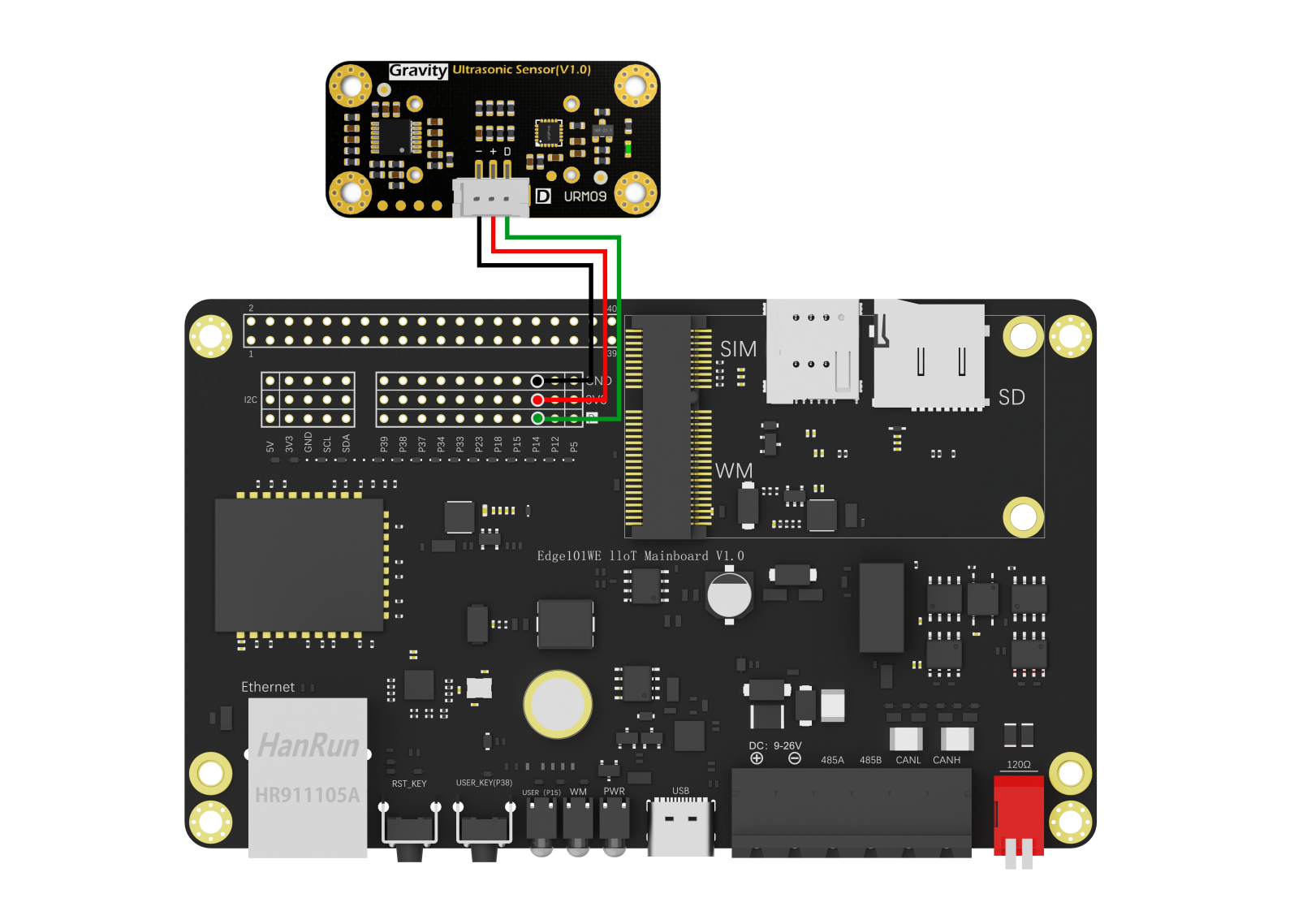
例程:脉冲信号宽度测量用于URM09超声波传感器读取
使用GPIO 14检测URM09超声波传感器测量距离输出的脉冲信号宽度,转换为距离值从串口打印出结果。
接线图:
/*!
This example is the ultrasonic distance measurement of the module.
Copyright [DFRobot](http://www.dfrobot.com), 2020
Copyright GNU Lesser General Public License
version V1.0
date 29/10/2020
*/
#define VELOCITY_TEMP(temp) ( ( 331.5 + 0.6 * (float)( temp ) ) * 100 / 1000000.0 ) // The ultrasonic velocity (cm/us) compensated by temperature
int16_t trigechoPin = 14;
uint16_t distance;
uint32_t pulseWidthUs;
void setup() {
Serial.begin(115200);
delay(100);
}
void loop() {
int16_t dist, temp;
pinMode(trigechoPin,OUTPUT);
digitalWrite(trigechoPin,LOW);
digitalWrite(trigechoPin,HIGH);//Set the trig pin High
delayMicroseconds(10); //Delay of 10 microseconds
digitalWrite(trigechoPin,LOW); //Set the trig pin Low
pinMode(trigechoPin,INPUT);//Set the pin to input mode
pulseWidthUs = pulseIn(trigechoPin,HIGH);//Detect the high level time on the echo pin, the output high level time represents the ultrasonic flight time (unit: us)
distance = pulseWidthUs * VELOCITY_TEMP(20) / 2.0;//The distance can be calculated according to the flight time of ultrasonic wave,/
//and the ultrasonic sound speed can be compensated according to the actual ambient temperature
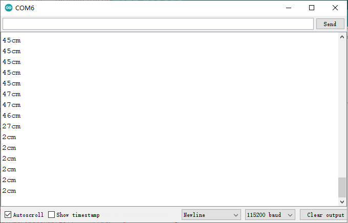
Serial.print(distance, DEC);
Serial.println("cm");
delay(500);
}
打印结果:
QQ截图20220225112336
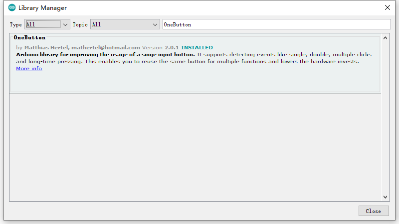
6.1.4 OneButton库,带消除按钮抖动和多种按键动作识别
在Arduino IDE里,打开Sketch->Include Library->manage libraries ,搜索OneButton库。下载并安装库。
首先引入头文件
#include "OneButton.h"
实例化一个OneButton对象
OneButton button(PIN_INPUT, true);
里面可以传三个参数:
pin : 按钮的pin脚
activeLow : true : 按下为低电平,false : 按下为高电平
pullupActive : true : 如果有上拉电阻就使能上拉电阻,false : 失能上拉电阻
然后为对象绑定单击、双击、长按等事件的回调, 单击、双击、长按等操作会触发这些回调。
API参考
例程:中断方式
程序在串口打印 Edge101WE 主板上的用户按钮事件,如果双击可改变主板上用户LED的状态。
#include "OneButton.h"

#define PIN_INPUT 38
#define PIN_LED 15


// Setup a new OneButton on pin PIN_INPUT
// The 2. parameter activeLOW is true, because external wiring sets the button to LOW when pressed.
OneButton button(PIN_INPUT, true);

// current LED state, staring with LOW (0)
int ledState = LOW;

// save the millis when a press has started.
unsigned long pressStartTime;

// In case the momentary button puts the input to HIGH when pressed:
// The 2. parameter activeLOW is false when the external wiring sets the button to HIGH when pressed.
// The 3. parameter can be used to disable the PullUp .
// OneButton button(PIN_INPUT, false, false);


ICACHE_RAM_ATTR void checkTicks()
{
  // include all buttons here to be checked
  button.tick(); // just call tick() to check the state.
}


// this function will be called when the button was pressed 1 time only.
void singleClick()
{
  Serial.println("singleClick() detected.");
} // singleClick


// this function will be called when the button was pressed 2 times in a short timeframe.
void doubleClick()
{
  Serial.println("doubleClick() detected.");

  ledState = !ledState; // reverse the LED
  digitalWrite(PIN_LED, ledState);
} // doubleClick


// this function will be called when the button was pressed 2 times in a short timeframe.
void multiClick()
{
  Serial.print("multiClick(");
  Serial.print(button.getNumberClicks());
  Serial.println(") detected.");

  ledState = !ledState; // reverse the LED
  digitalWrite(PIN_LED, ledState);
} // multiClick


// this function will be called when the button was pressed 2 times in a short timeframe.
void pressStart()
{
  Serial.println("pressStart()");
  pressStartTime = millis() - 1000; // as set in setPressTicks()
} // pressStart()


// this function will be called when the button was pressed 2 times in a short timeframe.
void pressStop()
{
  Serial.print("pressStop(");
  Serial.print(millis() - pressStartTime);
  Serial.println(") detected.");
} // pressStop()


// setup code here, to run once:
void setup()
{
  Serial.begin(115200);
  Serial.println("One Button Example with interrupts.");

  // enable the led output.
  pinMode(PIN_LED, OUTPUT); // sets the digital pin as output
  digitalWrite(PIN_LED, ledState);

  // setup interrupt routine
  // when not registering to the interrupt the sketch also works when the tick is called frequently.
  attachInterrupt(digitalPinToInterrupt(PIN_INPUT), checkTicks, CHANGE);

  // link the xxxclick functions to be called on xxxclick event.
  button.attachClick(singleClick);
  button.attachDoubleClick(doubleClick);
  button.attachMultiClick(multiClick);

  button.setPressTicks(1000); // that is the time when LongPressStart is called
  button.attachLongPressStart(pressStart);
  button.attachLongPressStop(pressStop);
}

// main code here, to run repeatedly:
void loop()
{
  // keep watching the push button, even when no interrupt happens:
  button.tick();

  // You can implement other code in here or just wait a while
  delay(10);
} // loop
6.2 脉冲计数器
6.2.1 脉冲计数器
脉冲计数器模块用于对输入脉冲的上升沿或下降沿进行计数。每个脉冲计数器单元均有一个带符号的 16-bit 计数寄存器以及两个通道,通过配置可以加减计数器。每个通道均有一个脉冲输入信号以及一个能够用于控制输入信号的控制信号。输入信号可以打开或关闭滤波功能。脉冲计数器有 8 组单元,各自独立工作,命名为 PULSE_CNT_Un。
每个单元有两个通道:ch0 和 ch1。这两个通道的功能相似。每个通道均有一个输入信号和一个控制输入信号,都能连接到芯片引脚。上升沿和下降沿中的计数工作模式可以分别进行增加、不增不减或者减少计数值的配置行为。对控制信号而言,通过配置硬件可以更改上升沿和下降沿的工作模式,包括:反转、禁止和保持。该计数器本身是一个带符号的 16-bit 加减计数器。它的值可以由软件直接读取,硬件通过将该值与一组比较器进行比较,可以产生中断。
计数器通道输入信号
一个通道里的两组输入信号能够以多种方式影响脉冲计数器:LCTRL_MODE 和 HCTRL_MODE 分别用于配置低控制信号和高控制信号;POS_MODE 和 NEG_MODE 分别用于配置输入信号的上升沿和下降沿。POS_MODE 和 NEG_MODE 配置为 1,计数器递增;若将它们配置为 2 时,则计数器递减;其它的值表示计数器保持原始值,既不递增,也不递减。当 LCTRL_MODE 或 HCTRL_MODE 为 0,表示不修改 NEG_MODE 和 POS_MODE 的工作模式;为 1 表示反转(即若原来计数器处于递增状态,当配置 POS_MODE 或 NEG_MODE 为 1 后,计数器将处于递减状态,反之亦然);其它的值会禁止计数器计数作用。
下表列出了一些关于上升沿对计数器作用的例子,包括低/高电平控制信号以及各种配置选择。为了清晰可见,下表数值后面的括号内添加了一些描述,x 代表了“无关项”。
POS_ MODE |
LCTRL_ MODE |
HCTRL_ MODE |
sig l→h when ctrl=0 |
sig l→h when ctrl=1 |
|---|---|---|---|---|
1 (inc) |
0 (-) |
0 (-) |
Inc ctr |
Inc ctr |
2 (dec) |
0 (-) |
0 (-) |
Dec ctr |
Dec ctr |
0 (-) |
x |
x |
No action |
No action |
1 (inc) |
0 (-) |
1 (inv) |
Inc ctr |
Dec ctr |
1 (inc) |
1 (inv) |
0 (-) |
Dec ctr |
Inc ctr |
2 (dec) |
0 (-) |
1 (inv) |
Dec ctr |
Inc ctr |
1 (inc) |
0 (-) |
2 (dis) |
Inc ctr |
No action |
1 (inc) |
2 (dis) |
0 (-) |
No action |
Inc ctr |
该表对下降沿 (sig h→l) 也同样适用,用 NEG_MODE 来代替 POS_MODE。
每个脉冲计数器单元在这 4 个输入中均有一个滤波器,可以滤除噪声。单元的 4 个输入信号可以通过置位PCNT_FILTER_EN_Un 来打开滤波功能。一旦滤波器被启动,任何宽度比 REG_FILTER_THRES_Un 个时钟周期窄的脉冲都会被过滤掉,这些被过滤掉的脉冲将不会对计数器起任何作用。
除了输入通道以外,软件也能对计数器进行一部分控制。比如通过置位 PCNT_CNT_PAUSE_Un,可以暂停计数器。通过置位 PCNT_PLUS_CNT_RST_Un 实现计数器清零功能。
观察点 PULSE_CNT 可以设置 5 个观察点,5 个观察点共用一个中断,可以通过各自的中断使能信号开启或屏蔽中断。
这些观察点分别是:
最大计数值。当 PULSE_CNT 大于等于 PCNT_CNT_H_LIM_Un 时,清空 PULSE_CNT。其中 PCNT_CNT_H_LIM_Un 应设为正数。
最小计数值。当 PULSE_CNT 小于等于 PCNT_CNT_L_LIM_Un 时,清空 PULSE_CNT。其中 PCNT_CNT_L_LIM_Un 应设为负数。
两个中间阈值。当 PULSE_CNT 等于 PCNT_THR_THRES0_Un 或者 PCNT_THR_THRES1_Un 时,产生相 应的 thr_event 信号。
零。当 PULSE_CNT 等于 0 时,产生相应的 thr_event 信号。
溢出中断 PCNT_CNT_THR_EVENT_Un_IN:该中断有 5 个中断源,即一个最大计数值中断,一个最小计数值中断,两个 中间阈值中断以及一个过零中断,它们可以通过各自的中断使能信号开启或屏蔽中断。
在工业中,脉冲计数器通常连接接近开关、光电开关、霍尔开关等传感器用于对工业现场进行计数,也可以外接按钮进行人工按键计数。
脉冲最高频率 40MHz。
6.2.2 计数器读取
API参考
pcnt_unit_config() - 配置脉冲计数器
语法
esp_err_t pcnt_unit_config(const pcnt_config_t *pcnt_config);
参数
参数 |
说明 |
值范围 |
|---|---|---|
const pcnt_config_t *pcnt_config |
单通道的脉冲计数器 参数配置指针(结构体指针) |
返回
返回值 |
说明 |
值范围 |
|---|---|---|
esp_err_t |
ESP_OK:配置成功ESP_ERR_INVALID_ARG:参数错误 |
pcnt_get_counter_value() - 获取脉冲计数器值
语法
esp_err_t pcnt_get_counter_value(pcnt_unit_t pcnt_unit, int16_t* count);
参数
参数 |
说明 |
值范围 |
|---|---|---|
pcnt_unit |
脉冲计数器单元数 |
0~7 |
count |
接受计数器值的指针 |
返回
返回值 |
说明 |
值范围 |
|---|---|---|
esp_err_t |
ESP_OK:配置成功ESP_ERR_INVALID_ARG:参数错误 |
pcnt_counter_pause() - 暂停脉冲计数单元的计数
语法
esp_err_t pcnt_counter_pause(pcnt_unit_t pcnt_unit);
参数
参数 |
说明 |
值范围 |
|---|---|---|
pcnt_unit |
脉冲计数器的单元号 |
0~7 |
返回
返回值 |
说明 |
值范围 |
|---|---|---|
esp_err_t |
ESP_OK:配置成功ESP_ERR_INVALID_ARG:参数错误 |
pcnt_counter_resume() - 恢复脉冲计数单元的计数
语法
esp_err_t pcnt_counter_resume(pcnt_unit_t pcnt_unit);
参数
参数 |
说明 |
值范围 |
|---|---|---|
pcnt_unit |
脉冲计数器的单元号 |
0~7 |
返回
返回值 |
说明 |
值范围 |
|---|---|---|
esp_err_t |
ESP_OK:配置成功ESP_ERR_INVALID_ARG:参数错误 |
pcnt_counter_clear() - 清除并将脉冲计数器的值重置为零
语法
esp_err_t pcnt_counter_clear(pcnt_unit_t pcnt_unit);
参数
参数 |
说明 |
值范围 |
|---|---|---|
pcnt_unit |
脉冲计数器的单元号 |
0~7 |
返回
返回值 |
说明 |
值范围 |
|---|---|---|
esp_err_t |
ESP_OK:配置成功ESP_ERR_INVALID_ARG:参数错误 |
pcnt_intr_enable() - 使能脉冲计数单元的脉冲计数中断
语法
esp_err_t pcnt_intr_enable(pcnt_unit_t pcnt_unit);
参数
参数 |
说明 |
值范围 |
|---|---|---|
pcnt_unit |
脉冲计数器的单元号 |
0~7 |
返回
返回值 |
说明 |
值范围 |
|---|---|---|
esp_err_t |
ESP_OK:配置成功ESP_ERR_INVALID_ARG:参数错误 |
每个脉冲计数器单元都有五个监视点事件,它们共享相同的中断。使用pcnt_event_enable()和pcnt_event_disable()配置事件。
pcnt_intr_disable() - 失能脉冲计数单元的脉冲计数中断
语法
esp_err_t pcnt_intr_disable(pcnt_unit_t pcnt_unit);
参数
参数 |
说明 |
值范围 |
|---|---|---|
pcnt_unit |
脉冲计数器的单元号 |
0~7 |
返回
返回值 |
说明 |
值范围 |
|---|---|---|
esp_err_t |
ESP_OK:配置成功ESP_ERR_INVALID_ARG:参数错误 |
pcnt_event_enable() - 启用脉冲计数单元的脉冲计数事件
语法
esp_err_t pcnt_event_enable(pcnt_unit_t unit, pcnt_evt_type_t evt_type);
参数
参数 |
说明 |
值范围 |
|---|---|---|
unit |
脉冲计数器的单元号 |
0~7 |
evt_type |
检测的事件类型 |
返回
返 回值 |
说明 |
值 范 围 |
|---|---|---|
esp_ err_t |
ESP_OK:配置成功ESP_ERR_INVALID_AR G:参数错误ESP_ERR_INVALID_STATE:pcnt驱动程序未初始化 |
pcnt_event_disable() - 失能脉冲计数单元的脉冲计数事件
语法
esp_err_t pcnt_event_disable(pcnt_unit_t unit, pcnt_evt_type_t evt_type);
参数
参数 |
说明 |
值范围 |
|---|---|---|
unit |
脉冲计数器的单元号 |
0~7 |
evt_type |
检测的事件类型 |
返回
返回值 |
说明 |
|---|---|
ESP_OK |
配置成功 |
ESP_ERR_INVALID_ARG |
参数错误 |
ESP_ERR_INVALID_STATE |
pcnt驱动程序未初始化 |
pcnt_set_event_value() - 设置PCNT单元的PCNT事件值
语法
esp_err_t pcnt_set_event_value(pcnt_unit_t unit, pcnt_evt_type_t evt_type, int16_t value);
参数
参数 |
说明 |
|---|---|
unit |
脉冲计数器的单元号 |
evt_type |
检测的事件类型 |
value |
PCNT事件的计数器值 |
返回
返 回值 |
说明 |
值 范 围 |
|---|---|---|
esp_ err_t |
ESP_OK:配置成功ESP_ERR_INVALID_AR G:参数错误ESP_ERR_INVALID_STATE:pcnt驱动程序未初始化 |
pcnt_get_event_value() - 读取PCNT单元的PCNT事件值
语法
esp_err_t pcnt_get_event_value(pcnt_unit_t unit, pcnt_evt_type_t evt_type, int16_t *value);
参数
参数 |
说明 |
值范围 |
|---|---|---|
unit |
脉冲计数器的单元号 |
0~7 |
evt_type |
检测的事件类型 |
|
value |
接受PCNT事件计数器值的指针 |
返回
返 回值 |
说明 |
值 范 围 |
|---|---|---|
esp_ err_t |
ESP_OK:配置成功ESP_ERR_INVALID_AR G:参数错误ESP_ERR_INVALID_STATE:pcnt驱动程序未初始化 |
pcnt_isr_register() - 注册PCNT中断处理程序
语法
esp_err_t pcnt_isr_register(void (*fn)(void *), void *arg, int intr_alloc_flags, pcnt_isr_handle_t *handle);
参数
参数 |
说明 |
值范围 |
|---|---|---|
fn |
中断处理函数 |
|
arg |
处理器函数的参数 |
|
intr_alloc_flags |
用于分配中断的标志。 |
|
handle |
返回句柄的指针。 |
返回
返 回值 |
说明 |
值 范 围 |
|---|---|---|
esp_ err_t |
ESP_OK:配置成功ESP_ERR_INVALID_ ARG:参数错误ESP_ERR_NOT_FOUND:找不到与标志匹配的中断 |
pcnt_set_pin() - 配置PCNT脉冲信号输入引脚和控制输入引脚
语法
esp_err_t pcnt_set_pin(pcnt_unit_t unit, pcnt_channel_t channel, int pulse_io, int ctrl_io);
参数
参数 |
说明 |
值范围 |
|---|---|---|
unit |
脉冲计数器的单元号 |
0~7 |
channel |
脉冲计数器的通道号 |
0,1 |
pulse_io |
用于分配中断的标志。 |
|
ctrl_io |
返回句柄的指针。 |
返回
返 回值 |
说明 |
值 范 围 |
|---|---|---|
esp_ err_t |
ESP_OK:配置成功ESP_ERR_INVALID_AR G:参数错误ESP_ERR_INVALID_STATE:pcnt驱动程序未初始化 |
pcnt_filter_enable() - 启用PCNT输入过滤器
语法
esp_err_t pcnt_filter_enable(pcnt_unit_t unit);
参数
参数 |
说明 |
值范围 |
|---|---|---|
unit |
脉冲计数器的单元号 |
0~7 |
返回
返 回值 |
说明 |
值 范 围 |
|---|---|---|
esp_ err_t |
ESP_OK:配置成功ESP_ERR_INVALID_AR G:参数错误ESP_ERR_INVALID_STATE:pcnt驱动程序未初始化 |
pcnt_filter_disable() - 失能PCNT输入过滤器
语法
esp_err_t pcnt_filter_disable(pcnt_unit_t unit);
参数
参数 |
说明 |
值范围 |
|---|---|---|
unit |
脉冲计数器的单元号 |
0~7 |
返回
返 回值 |
说明 |
值 范 围 |
|---|---|---|
esp_ err_t |
ESP_OK:配置成功ESP_ERR_INVALID_AR G:参数错误ESP_ERR_INVALID_STATE:pcnt驱动程序未初始化 |
pcnt_set_filter_value() - 设置PCNT过滤值
语法
esp_err_t pcnt_set_filter_value(pcnt_unit_t unit, uint16_t filter_val);
参数
参数 |
说明 |
值范围 |
|---|---|---|
unit |
脉冲计数器的单元号 |
0~7 |
filter_val |
PCNT信号滤波器值,计数器在APB_CLK周期。 |
maximum=1023 |
返回
返 回值 |
说明 |
值 范 围 |
|---|---|---|
esp_ err_t |
ESP_OK:配置成功ESP_ERR_INVALID_AR G:参数错误ESP_ERR_INVALID_STATE:pcnt驱动程序未初始化 |
pcnt_get_filter_value() - 读取PCNT过滤值
语法
esp_err_t pcnt_get_filter_value(pcnt_unit_t unit, uint16_t *filter_val);
参数
参数 |
说明 |
值范围 |
|---|---|---|
unit |
脉冲计数器的单元号 |
|
filter_val |
接受PCNT过滤器值的指针。 |
返回
返 回值 |
说明 |
值 范 围 |
|---|---|---|
esp_ err_t |
ESP_OK:配置成功ESP_ERR_INVALID_AR G:参数错误ESP_ERR_INVALID_STATE:pcnt驱动程序未初始化 |
pcnt_set_mode() - 设置PCNT计数器模式
语法
esp_err_t pcnt_set_mode(pcnt_unit_t unit, pcnt_channel_t channel, pcnt_count_mode_t pos_mode, pcnt_count_mode_t neg_mode, pcnt_ctrl_mode_t hctrl_mode, pcnt_ctrl_mode_t lctrl_mode);
参数
参数 |
说明 |
值范围 |
|---|---|---|
unit |
脉冲计数器的单元号 |
0~7 |
channel |
脉冲计数器的通道号 |
0,1 |
pos_mode |
检测到正边缘时,对应的计数器操作 |
|
neg_mode |
检测到负边缘时,对应的计数器操作 |
|
hctrl_mode |
当控制信号高电平时,对应的计数器操作 |
|
lctrl_mode |
当控制信号低电平时,对应的计数器操作 |
返回
返 回值 |
说明 |
值 范 围 |
|---|---|---|
esp_ err_t |
ESP_OK:配置成功ESP_ERR_INVALID_AR G:参数错误ESP_ERR_INVALID_STATE:pcnt驱动程序未初始化 |
pcnt_isr_handler_add() - 为指定的单元添加ISR处理程序
语法
esp_err_t pcnt_isr_handler_add(pcnt_unit_t unit, void(*isr_handler)(void *), void *args);
参数
参数 |
说明 |
值范围 |
|---|---|---|
unit |
脉冲计数器的单元号 |
0~7 |
isr_handler |
中断处理函数 |
|
args |
中断处理函数的参数 |
返回
返 回值 |
说明 |
值 范 围 |
|---|---|---|
esp_ err_t |
ESP_OK:配置成功ESP_ERR_INVALID_AR G:参数错误ESP_ERR_INVALID_STATE:pcnt驱动程序未初始化 |
pcnt_isr_service_install() - 安装PCNT ISR服务
语法
esp_err_t pcnt_isr_service_install(int intr_alloc_flags);
参数
参数 |
说明 |
值范围 |
|---|---|---|
unitintr_alloc_flags |
用于分配中断的标志 |
返回
返 回值 |
说明 |
值 范 围 |
|---|---|---|
esp_ err_t |
ESP_OK:配置成功ESP_ERR_INVALID_AR G:参数错误ESP_ERR_INVALID_STATE:pcnt驱动程序未初始化 |
pcnt_isr_service_uninstall() - 卸载PCNT ISR服务,释放相关资源
语法
void pcnt_isr_service_uninstall(void);
pcnt_isr_handler_remove() - 删除指定单元的ISR处理程序
语法
esp_err_t pcnt_isr_handler_remove(pcnt_unit_t unit);
参数
参数 |
说明 |
值范围 |
|---|---|---|
unit |
脉冲计数器的单元号 |
返回
返 回值 |
说明 |
值 范 围 |
|---|---|---|
esp_ err_t |
ESP_OK:配置成功ESP_ERR_INVALID_AR G:参数错误ESP_ERR_INVALID_STATE:pcnt驱动程序未初始化 |
例程:脉冲计数器中断例程
GPIO14是1Hz脉冲发生器的默认输出GPIO。
GPIO39是默认的脉冲输入GPIO。我们需要将GPIO14和GPIO39连接。通过GPIO39来对GPIO14输出脉冲进行计数。
GPIO5是默认的控制信号,当悬空或上拉到3.3V高电平,计数器的值会随着PWM脉冲的上升沿而增加,如果GPIO5接地,则计数器值减小。
(参考Arduino IDE例程 Examples -> Examples for Edge101WE -> PCNT:raw-latex:example:raw-latex:`\pcntInterrupt`)
/**
 * @file pcntInterrupt.ino
 * @brief This example is a pulse counter interrupt routine (Reference code:https://github.com/espressif/esp-idf/tree/master/examples/peripherals/pcnt/pulse_count_event)
 * @n This example uses the pulse counter module (PCNT) to count the rising edges of the PWM pulses generated by the LED Controller module (LEDC).
 * @n GPIO14 is the default output GPIO of the 1 Hz pulse generator.
 * @n GPIO39 is the default pulse input GPIO. We need to short GPIO14 and GPIO39.
 * @n GPIO5 is the default control signal, which can be left floating with internal pull up, or connected to Ground (If GPIO5 is left floating, the value of counter increases with the rising edges of the PWM pulses. If GPIO15 is connected to Ground, the value decreases).
 * @copyright  Copyright (c) 2010 DFRobot Co.Ltd (http://www.dfrobot.com)
 * @licence     The MIT License (MIT)
 * @author [yangfeng]<feng.yang@dfrobot.com>
 * @version  V1.0
 * @date  2021-03-12
 * @get from https://www.dfrobot.com
 */
#include "driver/ledc.h"
#include "driver/gpio.h"
#include "driver/pcnt.h"
#include "soc/pcnt_struct.h"
#define PCNT_TEST_UNIT      PCNT_UNIT_0
#define PCNT_H_LIM_VAL      10
#define PCNT_L_LIM_VAL     -10
#define PCNT_THRESH1_VAL    5
#define PCNT_THRESH0_VAL   -5

#define PCNT_INPUT_SIG_IO   39                     /*!< Pulse Input GPIO */
#define PCNT_INPUT_CTRL_IO  5                      /*!< Control GPIO HIGH=count up, LOW=count down */
#define LEDC_OUTPUT_IO      14                     /*!< Output GPIO of a sample 1 Hz pulse generator */

#define PCNT_EVT_STATE_THRES1             4        /*!< PCNT watch point event: threshold1 value event */
#define PCNT_EVT_STATE_THRES0             8        /*!< PCNT watch point event: threshold0 value event */
#define PCNT_EVT_STATE_LIM_L              16       /*!< PCNT watch point event: Minimum counter value */
#define PCNT_EVT_STATE_LIM_H              32       /*!< PCNT watch point event: Maximum counter value */
#define PCNT_EVT_STATE_ZERO               64       /*!< PCNT watch point event: counter value zero event */

xQueueHandle pcnt_evt_queue;                       /*!< A queue to handle pulse counter events */
pcnt_isr_handle_t user_isr_handle = NULL;          /*!< user's ISR service handle */

typedef struct {
  int unit;                                        /*!< the PCNT unit that originated an interrupt */
  uint32_t status;                                 /*!< information on the event type that caused the interrupt */
} pcnt_evt_t;

/** Decode what PCNT's unit originated an interrupt
 * and pass this information together with the event type
 * the main program using a queue.
 */
static void IRAM_ATTR pcnt_example_intr_handler(void *arg)
{
  uint32_t intr_status = PCNT.int_st.val;
  int i;
  pcnt_evt_t evt;
  portBASE_TYPE HPTaskAwoken = pdFALSE;

  for (i = 0; i < PCNT_UNIT_MAX; i++) {
    if (intr_status & (BIT(i))) {
      evt.unit = i;
      evt.status = PCNT.status_unit[i].val;        /*!< Save the PCNT event type that caused an interrupt to pass it to the main program */
      PCNT.int_clr.val = BIT(i);
      xQueueSendFromISR(pcnt_evt_queue, &evt, &HPTaskAwoken);
      if (HPTaskAwoken == pdTRUE) {
        portYIELD_FROM_ISR();
      }
    }
  }
}
static void ledc_init(void)
{
  int channel_PWM = 3;

  int resolution_PWM = 10;                         /*!< The PWM resolution is between 0 and 20, so the PWM resolution is between 0 and 2^10, which is 0 to 1024 */
  ledcSetup(channel_PWM, 1, resolution_PWM);       /*!< set pwm channel */
  ledcAttachPin(LEDC_OUTPUT_IO, channel_PWM);      /*!< Bind the LEDC channel to the specified IO port(GPIO14) for output */
  ledcWrite(channel_PWM, 512);
}

/** Initialize PCNT functions:
 *  - configure and initialize PCNT
 *  - set up the input filter
 *  - set up the counter events to watch
 */
static void pcnt_example_init(void)
{
  /*!< Prepare configuration for the PCNT unit */
  pcnt_config_t pcnt_config;
  pcnt_config.pulse_gpio_num = PCNT_INPUT_SIG_IO;  /*!< set gpio39 as pulse input gpio */
  pcnt_config.ctrl_gpio_num = PCNT_INPUT_CTRL_IO;  /*!< set gpio5 as control gpio */
  pcnt_config.channel = PCNT_CHANNEL_0;            /*!< use unit 0 channel 0 */
  pcnt_config.lctrl_mode = PCNT_MODE_REVERSE;      /*!< when control signal is low; reverse the primary counter mode(inc->dec/dec->inc) */
  pcnt_config.hctrl_mode = PCNT_MODE_KEEP;         /*!< when control signal is high; keep the primary counter mode */
  pcnt_config.pos_mode = PCNT_COUNT_INC;           /*!< increment the counter */
  pcnt_config.neg_mode = PCNT_COUNT_DIS;           /*!< keep the counter value */
  pcnt_config.counter_h_lim = PCNT_H_LIM_VAL;      /*!< Set the maximum limit values to watch */
  pcnt_config.counter_l_lim = PCNT_L_LIM_VAL;      /*!< Set the minimum limit values to watch */
  pcnt_config.unit = PCNT_TEST_UNIT;               /*!< Set pcnt unit */

  /*!< Initialize PCNT unit */
  pcnt_unit_config(&pcnt_config);

  /*!< Configure and enable the input filter */
  pcnt_set_filter_value(PCNT_TEST_UNIT, 100);
  pcnt_filter_enable(PCNT_TEST_UNIT);

  /*!< Set threshold 0 and 1 values and enable events to watch */
  pcnt_set_event_value(PCNT_TEST_UNIT, PCNT_EVT_THRES_1, PCNT_THRESH1_VAL);
  pcnt_event_enable(PCNT_TEST_UNIT, PCNT_EVT_THRES_1);
  pcnt_set_event_value(PCNT_TEST_UNIT, PCNT_EVT_THRES_0, PCNT_THRESH0_VAL);
  pcnt_event_enable(PCNT_TEST_UNIT, PCNT_EVT_THRES_0);

  /*!< Enable events on zero, maximum and minimum limit values */
  pcnt_event_enable(PCNT_TEST_UNIT, PCNT_EVT_ZERO);
  pcnt_event_enable(PCNT_TEST_UNIT, PCNT_EVT_H_LIM);
  pcnt_event_enable(PCNT_TEST_UNIT, PCNT_EVT_L_LIM);

  /*!< Initialize PCNT's counter */
  pcnt_counter_pause(PCNT_TEST_UNIT);
  pcnt_counter_clear(PCNT_TEST_UNIT);

  /*!< Register ISR handler and enable interrupts for PCNT unit */
  pcnt_isr_register(pcnt_example_intr_handler, NULL, 0, &user_isr_handle);
  pcnt_intr_enable(PCNT_TEST_UNIT);

  /*!< Everything is set up, now go to counting */
  pcnt_counter_resume(PCNT_TEST_UNIT);
}

void setup() {

  /*!< Initialize LEDC to generate sample pulse signal */
  ledc_init();

  /*!< Initialize PCNT event queue and PCNT functions */
  pcnt_evt_queue = xQueueCreate(10, sizeof(pcnt_evt_t));
  pcnt_example_init();
  Serial.begin(115200);
}

void loop() {
  int16_t count = 0;
  pcnt_evt_t evt;
  portBASE_TYPE res;
  while (1) {
    /* Wait for the event information passed from PCNT's interrupt handler.
     * Once received, decode the event type and print it on the serial monitor.
     */
    res = xQueueReceive(pcnt_evt_queue, &evt, 1000 / portTICK_PERIOD_MS);
    if (res == pdTRUE) {
      pcnt_get_counter_value(PCNT_TEST_UNIT, &count);
      Serial.printf("Event PCNT unit[%d]; cnt: %d\n", evt.unit, count);
      if (evt.status & PCNT_EVT_STATE_THRES1) {
          Serial.printf("THRES1 EVT\n");
      }
      if (evt.status & PCNT_EVT_STATE_THRES0) {
          Serial.printf("THRES0 EVT\n");
      }
      if (evt.status & PCNT_EVT_STATE_LIM_L) {
          Serial.printf("L_LIM EVT\n");
      }
      if (evt.status & PCNT_EVT_STATE_LIM_H) {
          Serial.printf("H_LIM EVT\n");
      }
      if (evt.status & PCNT_EVT_STATE_ZERO) {
          Serial.printf("ZERO EVT\n");
      }
    } else {
      pcnt_get_counter_value(PCNT_TEST_UNIT, &count);
      Serial.printf("Current counter value :%d\n", count);
    }
  }
  if(user_isr_handle) {
    /*!< Free the ISR service handle.*/
    esp_intr_free(user_isr_handle);
    user_isr_handle = NULL;
  }
}
串口输出为:
Current counter value :1
Current counter value :2
Current counter value :3
Current counter value :4
Event PCNT unit[0]; cnt: 5
THRES1 EVT
Current counter value :6
Current counter value :7
Current counter value :8
Current counter value :9
Event PCNT unit[0]; cnt: 0
H_LIM EVT
ZERO EVT
Current counter value :1
Current counter value :2
Current counter value :1
Event PCNT unit[0]; cnt: 0
ZERO EVT
Current counter value :-1
Current counter value :-2
Current counter value :-3
Current counter value :-4
Event PCNT unit[0]; cnt: -5
THRES0 EVT
Current counter value :-6
Current counter value :-7
Current counter value :-8
Current counter value :-9
Event PCNT unit[0]; cnt: 0
L_LIM EVT
ZERO EVT
Current counter value :-1
6.2.4 脉冲计数器用于读取旋转编码器例程
旋转编码器可输出AB两相脉冲,除了可记录脉冲个数,还可以通过AB脉冲上升或下降的先后顺序来表示正转或反转。
例程使用旋转编码器,编码器的 A、B、C输出分别连接到GPIO39、GPIO14、GPIO5端口。
通过串口打印出计数值,顺时针旋转加数值,反时针旋转减数值。C 输出为旋转编码器按下标志,当按下旋转编码器时,通过去抖处理后,串口打印按下动作。
函数简介:(这里对原有的脉冲计数函数进行了特定的封装用于旋转编码器)
API参考
init() - 配置脉冲计数器,并且使能计数中断
语法
bool init(const sRotaryEncoderConfig_t &config);
参数
参数 |
说明 |
值范围 |
|---|---|---|
config |
配置脉冲计数器的结构体 |
返回
返回值 |
说明 |
值范围 |
|---|---|---|
bool |
true:配置成功false:配置失败 |
setGlitchFilter() - 设置滤波器,如果参数maxGlitch的值大于0,则启用滤波器
语法
bool setGlitchFilter(uint16_t maxGlitch);
参数
参数 |
说明 |
值范围 |
|---|---|---|
maxGlitch |
PCNT信号的滤波值,计数器在APB_CLK周期。(0-1023) |
返回
返回值 |
说明 |
值范围 |
|---|---|---|
bool |
true:配置成功false:配置失败 |
start() - 开启(恢复)PCNT计数器计数
语法
bool start();
参数
无
返回
返回值 |
说明 |
值范围 |
|---|---|---|
bool |
true:启动成功false:启动失败 |
stop() - 暂停PCNT计数器计数
bool stop();
参数
无
返回
返回值 |
说明 |
值范围 |
|---|---|---|
bool |
true:停止成功false:停止失败 |
getCounterValue() - 获取计数器计数值,返回计数值
语法
int getCounterValue();
参数
无
返回
返回值 |
说明 |
值范围 |
|---|---|---|
int |
计数值 |
例程:旋转编码器计数
接线图:
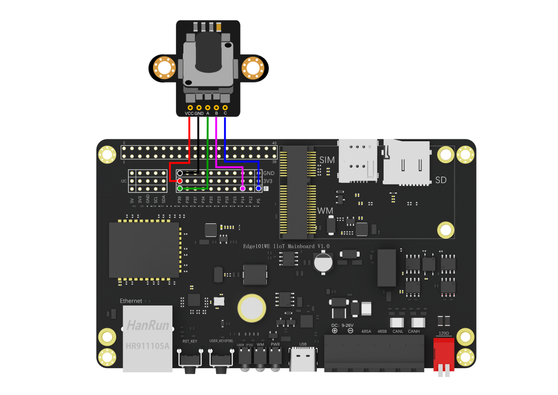
(参考Arduino IDE例程 Examples -> Examples for Edge101WE -> PCNT:raw-latex:example:raw-latex:`\rotaryEncoder`)
/**
 * @file rotaryEncoder.ino
 * @brief The rotary encoder can output AB two-phase pulse, in addition to recording the number of pulses, but also through the sequence of AB pulse rise or fall to indicate the forward or reverse. (routine reference to https://github.com/espressif/esp-idf/tree/master/examples/peripherals/pcnt/rotary_encoder)
 * @n Routine use of rotary encoder (https://www.dfrobot.com.cn/goods-1421.html), A, B, C respectively connected to the output GPIO39, GPIO14, GPIO5 port.
 * @n Print the calculated value through the serial port, rotate clockwise to add value, rotate counterclockwise to subtract value. C output is the symbol of rotary encoder press down. When the rotary encoder is pressed down, the serial port prints the press down action after shaking off.
 * @copyright  Copyright (c) 2010 DFRobot Co.Ltd (http://www.dfrobot.com)
 * @licence     The MIT License (MIT)
 * @author [yangfeng]<feng.yang@dfrobot.com>
 * @version  V1.0
 * @date  2021-03-08
 * @get from https://www.dfrobot.com
 */
#include "DFRobot_EC11.h"
#define ENCODER_PIN_A  39
#define ENCODER_PIN_B  14
#define BUTTON_PIN     5

int pcnt_unit = 0;

/* rotary encoder configuration */
sRotaryEncoderConfig_t config = {(pcnt_unit_t)pcnt_unit,ENCODER_PIN_A,ENCODER_PIN_B,0};

DFRobot_EC11 EC11;

uint8_t buttonFlag = 0;

void isButtonPushDown(void)
{
  /* key-vibration eliminate */
  if (!digitalRead(BUTTON_PIN)) {
    delay(50);
    if (!digitalRead(BUTTON_PIN)){
      if(buttonFlag == 0){
        buttonFlag =1;
      }
    }
  }

}
void setup() {
  Serial.begin(115200);

  while(!EC11.init(config)){//Configure pulse counter
    Serial.println("init failed!");
    delay(1000);
  }
  while(!EC11.setGlitchFilter(1023)){//Example Set the PCNT filter value.   maxGlitch is a 10-bit value, so the maximum value should be limited to 1023.
    Serial.println("set glitch filter failed");
    delay(1000);
  }
  EC11.start();
  pinMode(BUTTON_PIN, INPUT);
  attachInterrupt(digitalPinToInterrupt(BUTTON_PIN), isButtonPushDown, FALLING);//Enable external interrupt
}

void loop() {
  if(buttonFlag == 1){
    buttonFlag =0;
    Serial.printf("The button has been pressed\n");
  }
  Serial.printf("Encoder value: %d\n",EC11.getCounterValue());//Serial port output count value
  delay(1000);
}
6.3 LED PWM输出
LED PWM 主要用于控制 LED 的亮度和颜色,也可以产生 PWM 信号用于其他用途,例如工业上控制加热器。LED_PWM 有 16 路通道,这 16 路通道能够产生独立的数字波形来驱动设备。
API参考
ledcSetup() - LEDC设置函数
语法
double ledcSetup(uint8_t channel, double freq, uint8_t resolution_bits)
参数
传入值 |
说明 |
值范围 |
|---|---|---|
uint8_t channel |
通道号 |
0 ~ 15 |
double freq |
频率 |
设置频率 |
uint8_t resolution_bits |
计数位数 |
0 ~ 20 |
resolution_bits值决定后面ledcWrite方法中占空比的最大值,如该值写10,则占空比最大可写2^10-1=1023 。 通道最终频率 = 时钟频率 / ( 分频系数 * ( 2^计数位数 ) );(分频系数最大为1024)
返回
返回值 |
说明 |
值范围 |
|---|---|---|
double |
最终频率 |
ledcWrite() - LEDC写函数
指定通道输出一定占空比的波形。
语法
void ledcWrite(uint8_t channel, uint32_t duty)
参数
传入值 |
说明 |
值范围 |
|---|---|---|
uint8_t channel |
通道号 |
0 ~ 15 |
uint32_t duty |
占空比 |
0 ~ 100 |
返回
无
ledcWriteTone() - LEDC音频写函数
当外接无源蜂鸣器的时候可用该函数,发出某种音色(根据频率不同而不同)
double ledcWriteTone(uint8_t channel, double freq)
参数
传入值 |
说明 |
值范围 |
|---|---|---|
uint8_t channel |
通道号 |
0 ~ 15 |
double freq |
频率 |
返回
返回值 |
说明 |
值范围 |
|---|---|---|
double |
设置的频率 |
ledcWriteNote() - LEDC调式写函数
该方法是上面方法的进一步封装,可以直接输出指定调式和音阶声音的信号。
语法
double ledcWriteNote(uint8_t channel, note_t note, uint8_t octave)
参数
传入值 |
说 明 |
值范围 |
|---|---|---|
uint8_t channel |
通 道 号 |
0 ~ 15 |
note_t note |
调 式 |
NOTE_C, NOTE_Cs, NOTE_D, NOTE_Eb, NOTE_E, NOTE_F, NOTE_Fs, NOTE_G, NOTE_Gs, NOTE_A, NOTE_Bb, NOTE_B |
uint8_t octave |
音 阶 |
0~7 |
返回 无
ledcRead() - 返回指定通道占空比的值
语法
uint32_t ledcRead(uint8_t channel)
参数
传入值 |
说明 |
值范围 |
|---|---|---|
uint8_t channel |
通道号 |
0 ~ 15 |
返回
返回值 |
说明 |
值范围 |
|---|---|---|
uint32_t |
占空比的值 |
ledcReadFreq() - 返回指定通道当前频率
如果当前占空比为0 则该方法返回0
double ledcReadFreq(uint8_t channel)
参数 |
说明 |
值范围 |
|---|---|---|
uint8_t channel |
通道号 |
0 ~ 15 |
返回
返回值 |
说明 |
值范围 |
|---|---|---|
double |
当前频率 |
ledcAttachPin() - 绑定
将LEDC通道投射到指定IO口上。
语法
void ledcAttachPin(uint8_t pin, uint8_t channel)
参数
传入值 |
说明 |
值范围 |
|---|---|---|
uint8_t pin |
GPIO端口号 |
0 ~ 39 |
uint8_t channel |
通道号 |
0 ~ 15 |
返回
无
ledcDetachPin() - 解除绑定
解除IO口的LEDC功能。
语法
void ledcDetachPin(uint8_t pin)
参数
传入值 |
说明 |
值范围 |
|---|---|---|
uint8_t pin |
GPIO端口号 |
0 ~ 39 |
返回
无
例程:GPIO15上的板载用户LED亮度渐变示例代码
(参考Arduino IDE例程 Examples -> Examples for Edge101WE -> ESP32:raw-latex:AnalogOut:raw-latex:`\LEDCSoftwareFade`)
程序让主板上的用户LED产生渐变的亮灭效果
// 使用LED PWM的通道0
#define LEDC_CHANNEL_0     0

// 13bit定时器分辨率
#define LEDC_TIMER_13_BIT  13

// 设置PWM频率为5000Hz
#define LEDC_BASE_FREQ     5000

// 使用GPIO15作为PWM输出
#define LED_PIN            15

int brightness = 0;    // LED亮度
int fadeAmount = 5;    // 淡入是多少点

// 模拟Arduino标准库的analogWrite函数
// value has to be between 0 and valueMax
void ledcAnalogWrite(uint8_t channel, uint32_t value, uint32_t valueMax = 255) {
  // calculate duty, 8191 from 2 ^ 13 - 1
  uint32_t duty = (8191 / valueMax) * min(value, valueMax);

  // write duty to LEDC
  ledcWrite(channel, duty);
}

void setup() {
  // Setup timer and attach timer to a led pin
  ledcSetup(LEDC_CHANNEL_0, LEDC_BASE_FREQ, LEDC_TIMER_13_BIT);
  ledcAttachPin(LED_PIN, LEDC_CHANNEL_0);
}

void loop() {
  // set the brightness on LEDC channel 0
  ledcAnalogWrite(LEDC_CHANNEL_0, brightness);

  // change the brightness for next time through the loop:
  brightness = brightness + fadeAmount;

  // reverse the direction of the fading at the ends of the fade:
  if (brightness <= 0 || brightness >= 255) {
    fadeAmount = -fadeAmount;
  }
  // wait for 30 milliseconds to see the dimming effect
  delay(30);
}
通道和引脚是映射关系: 一个通道可对应多个引脚,一个引脚只能绑定一个通道
ledcAttachPin(14, 8); //设置LEDC通道8在IO14上输出
我们可以看到,输出pwm的方法函数也是设置的通道而不是引脚
例程:控制 RGB LED
代码使用3个PWM输出控制一颗RGB LED的颜色和亮度编号。
接线图:
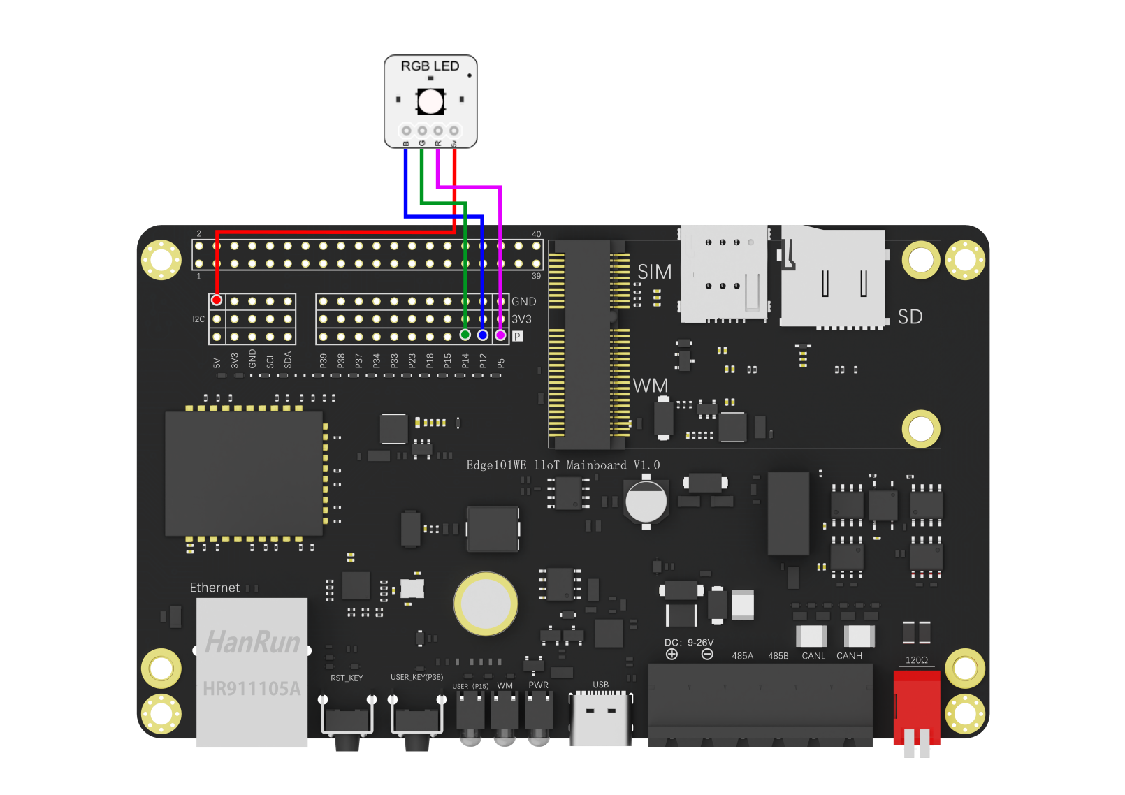
(参考Arduino IDE例程 Examples -> Examples for Edge101WE -> ESP32:raw-latex:AnlogOut:raw-latex:`\ledcWrite`_RGB)
// Set up the rgb led names
uint8_t ledR = 5;
uint8_t ledG = 14;
uint8_t ledB = 12;

uint8_t ledArray[3] = {1, 2, 3}; // three led channels

const boolean invert = true; // set true if common anode, false if common cathode

uint8_t color = 0;          // a value from 0 to 255 representing the hue
uint32_t R, G, B;           // the Red Green and Blue color components
uint8_t brightness = 255;  // 255 is maximum brightness, but can be changed.  Might need 256 for common anode to fully turn off.

// the setup routine runs once when you press reset:
void setup()
{
  Serial.begin(115200);
  delay(10);

  ledcAttachPin(ledR, 1); // assign RGB led pins to channels
  ledcAttachPin(ledG, 2);
  ledcAttachPin(ledB, 3);

  // Initialize channels
  // channels 0-15, resolution 1-16 bits, freq limits depend on resolution
  // ledcSetup(uint8_t channel, uint32_t freq, uint8_t resolution_bits);
  ledcSetup(1, 12000, 8); // 12 kHz PWM, 8-bit resolution
  ledcSetup(2, 12000, 8);
  ledcSetup(3, 12000, 8);
}

// void loop runs over and over again
void loop()
{
  Serial.println("Send all LEDs a 255 and wait 2 seconds.");
  // If your RGB LED turns off instead of on here you should check if the LED is common anode or cathode.
  // If it doesn't fully turn off and is common anode try using 256.
  ledcWrite(1, 255);
  ledcWrite(2, 255);
  ledcWrite(3, 255);
  delay(2000);
  Serial.println("Send all LEDs a 0 and wait 2 seconds.");
  ledcWrite(1, 0);
  ledcWrite(2, 0);
  ledcWrite(3, 0);
  delay(2000);

  Serial.println("Starting color fade loop.");

  for (color = 0; color < 255; color++) { // Slew through the color spectrum

    hueToRGB(color, brightness);  // call function to convert hue to RGB

    // write the RGB values to the pins
    ledcWrite(1, R); // write red component to channel 1, etc.
    ledcWrite(2, G);
    ledcWrite(3, B);

    delay(100); // full cycle of rgb over 256 colors takes 26 seconds
  }

}

// Courtesy http://www.instructables.com/id/How-to-Use-an-RGB-LED/?ALLSTEPS
// function to convert a color to its Red, Green, and Blue components.

void hueToRGB(uint8_t hue, uint8_t brightness)
{
  uint16_t scaledHue = (hue * 6);
  uint8_t segment = scaledHue / 256; // segment 0 to 5 around the
  // color wheel
  uint16_t segmentOffset =
    scaledHue - (segment * 256); // position within the segment

  uint8_t complement = 0;
  uint16_t prev = (brightness * ( 255 -  segmentOffset)) / 256;
  uint16_t next = (brightness *  segmentOffset) / 256;

  if (invert)
  {
    brightness = 255 - brightness;
    complement = 255;
    prev = 255 - prev;
    next = 255 - next;
  }

  switch (segment ) {
    case 0:      // red
      R = brightness;
      G = next;
      B = complement;
      break;
    case 1:     // yellow
      R = prev;
      G = brightness;
      B = complement;
      break;
    case 2:     // green
      R = complement;
      G = brightness;
      B = next;
      break;
    case 3:    // cyan
      R = complement;
      G = prev;
      B = brightness;
      break;
    case 4:    // blue
      R = next;
      G = complement;
      B = brightness;
      break;
    case 5:      // magenta
    default:
      R = brightness;
      G = complement;
      B = prev;
      break;
  }
}
SigmaDelta输出
主板具有一个二阶 sigma-delta 调制模块。此驱动程序可配置 sigma-delta 模块的通道。八个独立的 sigma-delta 调制信道用 sigmadelta channel进行标识。每个通道都能够输出 sigma-delta 调制模块生成的二进制硬件信号。
通常,如果将sigma-delta信号连接到LED,则不必在它们之间添加任何滤波器(因为我们的眼睛自然是低通滤波器)。但是,如果要检查实际电压或观看模拟波形,则需要设计一个模拟低通滤波器。另外,建议使用有源滤波器代替无源滤波器以获得更好的隔离并且不会降低太多电压。
例如,您可以将以下Sallen-Key拓扑低通滤波器作为参考。

Sallen-Key低通滤波器
API参考
sigmaDeltaSetup() - 设置sigma delta调制
语法
uint32_t sigmaDeltaSetup(uint8_t channel, uint32_t freq);
参数
传入值 |
说明 |
值范围 |
|---|---|---|
uint8_t channel |
通道号 |
0 ~ 7 |
uint32_t freq |
频率 |
1220 ~ 312500 |
返回
返回值 |
说明 |
值范围 |
|---|---|---|
uint32_t |
实际设定的频率 |
实际上,它不是直接设置频率,而是根据频率来设置时钟的分频比。分频比(预分频比)由公式prescale =(10000000 /(freq * 32))-1表示。如果预分频比大于0xff,它将为0xff。
因此,将freq设置为小于1220或大于312500的值分别导致1220和312500。
sigmaDeltaAttachPin() - 连接用于sigma-delta调制的引脚和通道
语法
void sigmaDeltaAttachPin(uint8_t pin, uint8_t channel);
参数
传入值 |
说明 |
值范围 |
|---|---|---|
uint8_t pin |
引脚 |
0 ~ 39 |
uint8_t channel |
通道号 |
0 ~ 7 |
返回
无
sigmaDeltaDetachPin() - 断开用于sigma-delta调制的引脚和通道
语法
void sigmaDeltaDetachPin(uint8_t pin);
参数
传入值 |
说明 |
值范围 |
|---|---|---|
uint8_t pin |
引脚 |
0 ~ 39 |
返回
无
sigmaDeltaWrite() - 使用sigma-delta调制以指定的占空比输出
语法
void sigmaDeltaWrite(uint8_t channel, uint8_t duty);
参数
传入值 |
说明 |
值范围 |
|---|---|---|
uint8_t channel |
引脚 |
0 ~ 7 |
uint8_t duty |
通道号 |
0 ~ 255 |
返回
无
sigmaDeltaRead() - 获取为sigma-delta调制通道指定的占空比
语法
uint8_t sigmaDeltaRead(uint8_t channel);
参数
传入值 |
说明 |
值范围 |
|---|---|---|
uint8_t channel |
引脚 |
0 ~ 7 |
返回
返回值 |
说明 |
值范围 |
|---|---|---|
uint8_t |
占空比 |
例程:SigmaDelta
程序让GPIO15的用户LED从灭到最亮的渐变,当达到最亮时熄灭。和LEDC代码比较,LEDC代码是频率不变,通过改变占空比来调整输出,而sigmaDelta是通过调整波形的频率来控制。
(参考Arduino IDE例程 Examples -> Examples for Edge101WE -> ESP32:raw-latex:AnlogOut:raw-latex:`\SigmaDelta`)
void setup()
{
    //setup channel 0 with frequency 312500 Hz
    sigmaDeltaSetup(0, 312500);
    //attach pin 15 to channel 0
    sigmaDeltaAttachPin(15,0);
    //initialize channel 0 to off
    sigmaDeltaWrite(0, 0);
}

void loop()
{
    //slowly ramp-up the value
    //will overflow at 256
    static uint8_t i = 0;
    sigmaDeltaWrite(0, i++);
    delay(10);
}
6.4 ADC 模数转换
Edge101WE 主板具备 12-bit SAR ADC,共支持6 个模拟通道输入,采样速度2 Msps。同一时间每个ADC只能采集一个通道。
注意:在WiFi开启时ADC2不能使用。
40P IN接口号 |
引脚名称 |
GPIO功能 |
ADC功能 |
通信功能 |
复用功能 |
|---|---|---|---|---|---|
3 |
GPI O18:raw- latex:`I`2C-SDA |
GPIO18 可作为输 入和输出 |
I2C-SDA |
Gravity I2C-SDA |
|
5 |
GPI O23:raw- latex:`I`2C-SCL |
GPIO23 可作为输 入和输出 |
I2C-SCL |
Gravity I2C-SCL |
|
8 |
GPIO33:r aw-latex :ADC1 _CH5:ra w-latex: U1TXD |
GPIO33 可作为输 入和输出 |
U1TXD |
PCIe插 槽U1TXD |
|
10 |
IN34:r aw-latex :ADC1 _CH6:ra w-latex: U1RXD |
GP IO34只能 作为输入 |
U1RXD |
PCIe插 槽U1RXD |
|
11 |
GPIO1 5:raw-la tex:AD C2_CH3 |
GPIO15 可作为输 入和输出 |
ADC2_CH3 |
板载 用户LED |
|
19 |
GP IO12:raw -latex:` ADC2`_ CH5:raw- latex:SPI-SDO |
GPIO12 可作为输 入和输出 |
ADC2_CH5 |
SPI-SDO |
Gravity SPI-SDO |
21 |
IN39:raw -latex:` ADC1`_ CH3:raw- latex:SPI-SDI |
GP IO39只能 作为输入 |
ADC1_CH3 |
SPI-SDI |
Gravity SPI-SDI |
23 |
GP IO14:raw -latex:` ADC2`_ CH6:raw- latex:SPI-CLK |
GPIO14 可作为输 入和输出 |
ADC2_CH6 |
SPI-CLK |
Gravity SPI-CLK |
26 |
GP IO5:raw- latex:VSPICS0 |
GPIO5 可作为输 入和输出 |
SPICS0 |
Gravity SPICS0 |
|
38 |
IN3 7:raw-la tex:AD C1_CH1 |
GP IO37只能 作为输入 |
ADC1_CH1 |
||
40 |
IN3 8:raw-la tex:AD C1_CH2 |
GP IO38只能 作为输入 |
ADC1_CH2 |
板载 用户按钮 |
API参考
analogRead() - 获取指定IO口的模拟电压数据
获取指定IO口的模拟电压数据(该方法将阻塞直到采集完成)。
语法
uint16_t analogRead(uint8_t pin)
参数
传入值 |
说明 |
值范围 |
|---|---|---|
uint8_t pin |
GPIO端口号 |
具备ADC功能的GPIO |
返回
返回值 |
说明 |
值范围 |
|---|---|---|
uint16_t |
读取到的模拟量值 |
analogReadResolution(uint8_t bits) - 设置模拟数据读取分辨率
语法
void analogReadResolution(uint8_t bits)
参数
传入值 |
说明 |
值范围 |
|---|---|---|
uint8_t bits |
设置模拟数据读取分辨率(默认为12) |
1 ~ 16 |
返回
无
analogSetWidth() - 设置ADC采样分辨率
语法
void analogSetWidth(uint8_t bits)
参数
传入值 |
说明 |
值范围 |
|---|---|---|
uint8_t bits |
设置模拟数据读取分辨率(默认为12) |
9 ~ 12 |
返回
无
analogSetCycles() - 设置单次采样的周期
语法
void analogSetCycles(uint8_t cycles)
参数
传入值 |
说明 |
值范围 |
|---|---|---|
uint8_t cycles |
设置单次采样的周期(默认为8) |
1 ~ 255 |
返回
无
analogSetSamples() - 设置单次采样的实际采样次数
语法
void analogSetSamples(uint8_t samples)
该项的设置相当于提高了ADC的灵敏度,比如该值为2,则采样获得数据就是真实数据的2倍。
参数
传入值 |
说明 |
值范围 |
|---|---|---|
uint8_t samples |
设置单次采样的实际采样次数(默认为1) |
1 ~ 255 |
返回
无
analogSetClockDiv() - 设置ADC时钟分频系数
语法
void analogSetClockDiv(uint8_t clockDiv)
参数
传入值 |
说明 |
值范围 |
|---|---|---|
uint8_t clockDiv |
设置ADC时钟分频系数(默认为1) |
1 ~ 255 |
返回
无
analogSetAttenuation() - 设置ADC全局输入衰减
语法
void analogSetAttenuation(adc_attenuation_t attenuation)
参数
传入值 |
说明 |
值范围 |
|---|---|---|
adc_attenuation_t attenuation |
设置ADC全局输 入衰减(默认为11db) |
ADC_0db, ADC_2_5db, ADC_6db, ADC_11db |
返回
无
注:
当 VDD_A 为 3.3V 时: 0dB 下量程最大为 1.1V 2.5dB 下量程最大为 1.5V 6dB 下量程最大为 2.2V 11dB 下量程最大为 3.9V(最大可以采集到3.3V电压)
analogSetPinAttenuation() - 设置指定GPIO的输入衰减
void analogSetPinAttenuation(uint8_t pin, adc_attenuation_t attenuation)
参数
传入值 |
说明 |
值范围 |
|---|---|---|
uint8_t pin |
GPIO端口号 |
具备ADC功能的GPIO |
adc_attenuation_t attenuation |
输入衰减 |
ADC_0db, ADC_2_5db, ADC_6db, ADC_11db |
返回
无
以下为非阻塞采样
adcAttachPin() - 将IO口连接到ADC
语法
bool adcAttachPin(uint8_t pin)
参数
传入值 |
说明 |
值范围 |
|---|---|---|
uint8_t pin |
GPIO端口号 |
具备ADC功能的GPIO |
返回
返回值 |
说明 |
值范围 |
|---|---|---|
bool |
启动成功返回 1 |
adcStart() - 开启采样与转换
语法
bool adcStart(uint8_t pin)
参数
传入值 |
说明 |
值范围 |
|---|---|---|
uint8_t pin |
GPIO端口号 |
具备ADC功能的GPIO |
返回
返回值 |
说明 |
值范围 |
|---|---|---|
bool |
启动成功返回 1 |
adcBusy(uint8_t pin) - 检查采样与转换是否完成
语法
bool adcBusy(uint8_t pin)
参数
传入值 |
说明 |
值范围 |
|---|---|---|
uint8_t pin |
GPIO端口号 |
具备ADC功能的GPIO |
返回
返回值 |
说明 |
值范围 |
|---|---|---|
bool |
正在转换返回 1 |
adcEnd() - 读取采集到的数据
如果未完成将阻塞至完成。
语法
uint16_t adcEnd(uint8_t pin)
参数
传入值 |
说明 |
值范围 |
|---|---|---|
uint8_t pin |
GPIO端口号 |
具备ADC功能的GPIO |
返回
返回值 |
说明 |
值范围 |
|---|---|---|
uint16_t |
转换结果 |
setCalibrationMode() - 设置ADC校准模式
ADC 提供了三种校准模式(两点校准、使用 efuse 内写入的 VREF 校准、使用用户指定的 VREF 进行校准),在使用前可以使用 adcCalCheckEfuse() 方法查看当前主板支持哪种校准模式。
语法
bool setCalibrationMode(uint16_t mode)
参数
传入值 |
说明 |
值范围 |
|---|---|---|
uint16_t mode |
校准模式 |
EFUSE_TP、EFUSE_VREF、 DEFAULT_VREF(分别对应上述的三种模式) |
返回
返回值 |
说明 |
值范围 |
|---|---|---|
bool |
模式配置的结果 |
返回true表示成功,返回false表示失败 |
adcCalCheckEfuse() - 检查ADC校准值是否烧入eFuse
检查ADC参考电压或两点校准值是否已经烧入到当前主板的eFuse。
语法
bool adcCalCheckEfuse(eEsp32ADCCalValue_t valueType)
参数
传入值 |
说明 |
值范围 |
|---|---|---|
eEsp32ADCCalValue_t valueType |
校 准值 类型 |
ADC_CAL_VAL_EFUSE_VREF 、ADC_CAL_VAL_EFUSE_TP |
返回
返 回值 |
说明 |
值范围 |
|---|---|---|
esp_ err_t |
检查 结果 |
ESP_OK:eFuse支持该校准模式ESP_ERR_NOT _SUPPORTED:eFuse不支持该校准模式ESP_ERR_INVALID_ARG: 无效参数(ADC_CAL_VAL_DEFAULT_VREF) |
isLookuptable() - 选择是否使用查表校准
在配置ADC衰减为ADC_ATTEN_DB_11,选择是否使用查表校准。
语法
void isLookuptable(bool mode)
参数
传入值 |
说明 |
值范围 |
|---|---|---|
bool mode |
模式选择 |
true表示使用,false表示不使用 |
返回 无
adcInit() - ADC配置以及校准配置的初始化
该函数将ADC在特定衰减下的特性,生成ADC-电压曲线,其形式为 y = coeffA * x + coeffB 。可以基于两点值,eFuse Vref,或default Vref,校准值将按此顺序排列。
语法
bool adcInit(adc_unit_t unit, adc_channel_t channel, adc_atten_t atten,
               adc_bits_width_t bitWidth, uint32_t defaultVref)
参数
传入值 |
说明 |
值范围 |
|---|---|---|
adc_unit_t unit |
ADC单元 |
ADC_UNIT_1 、ADC_UNIT_2 |
adc_channel_t channel |
ADC通道 |
如下说明 |
adc_atten_t atten |
衰 减的特点 |
ADC_ATTEN_DB_0、ADC_ATTEN_ DB_2_5、ADC_ATTEN_DB_6、ADC_ATTEN_DB_11 |
ad c_bits_width_t bitWidth |
ADC的 位宽配置 |
ADC_WIDTH_BIT_9、ADC_WIDTH_BIT _10、ADC_WIDTH_BIT_11、ADC_WIDTH_BIT_12 |
uint32_t defaultVref |
默认ADC参 考电压值 |
默认ADC参考电压 mV(仅在ESP32中,在eFuse值不可用时使用) |
ADC1(类型:adc1_channel_t) |
ADC2(类型:adc2_channel_t) |
|---|---|
ADC1_CHANNEL_0 —GPIO36 |
ADC2_CHANNEL_0—GPIO4 |
ADC1_CHANNEL_1—GPIO37 |
ADC2_CHANNEL_1—GPIO0 |
ADC1_CHANNEL_2—GPIO38 |
ADC2_CHANNEL_2—GPIO2 |
ADC1_CHANNEL_3—GPIO36 |
ADC2_CHANNEL_3—GPIO15 |
ADC1_CHANNEL_4—GPIO39 |
ADC2_CHANNEL_4—GPIO13 |
ADC1_CHANNEL_5—GPIO32 |
ADC2_CHANNEL_5—GPIO12 |
ADC1_CHANNEL_6—GPIO33 |
ADC2_CHANNEL_6—GPIO14 |
ADC1_CHANNEL_7—GPIO34 |
ADC2_CHANNEL_7—GPIO27 |
ADC1_CHANNEL_MAX—GPIO35 |
ADC2_CHANNEL_8—GPIO25 |
ADC2_CHANNEL_9—GPIO26 |
|
ADC2_CHANNEL_MAX |
返回
返回值 |
说明 |
值范围 |
|---|---|---|
bool |
初始化结果 |
ture 初始化成功 false 初始化失败 |
adcCalGetVoltage() - 读取ADC并将读数转换为以mV为单位的电压
该函数读取ADC,然后将原始读数转换为基于提供的特性的电压mV。读取的ADC也是由这些特征决定的。读取的电压值将会用类的成员变量储存,用户可直接访问此变量获取数据。
语法
esp_err_t adcCalGetVoltage()
参数
无
返回
返 回值 |
说明 |
值范围 |
|---|---|---|
esp_ err_t |
读取 结果 |
ESP_OK:ADC 读取、转换为mV成功ESP_ERR_TIME OUT:ADC读取超时ESP_ERR_INVALID_ARG:无效参数导致错误 |
例程:ADC单通道采集
void setup()
{
  Serial.begin(115200);
  Serial.println();
}

void loop()
{
  int vtmp = analogRead(37); //GPIO37 ADC1_CH1获取电压

  Serial.printf("sample value: %d\n", vtmp);
  Serial.printf("voltage: %.3fV\n", vtmp * 3.26 / 4095);
  delay(500);
}
将程序烧写到主板后,在GPIO37脚连接一个电位器,调节输入的电压。串口将打印出测量到的原始电压数字量和电压值。
sample value: 0
voltage: 0.000V
sample value: 79
voltage: 0.063V
sample value: 203
voltage: 0.162V
sample value: 241
voltage: 0.192V
sample value: 1882
voltage: 1.498V
sample value: 2842
voltage: 2.262V
sample value: 3152
voltage: 2.509V
sample value: 4095
voltage: 3.260V
例程:ADC校准
(参考Arduino IDE例程 Examples -> Examples for Edge101WE -> ADCCorrect:raw-latex:example:raw-latex:`\adcCorrect`)
/**
 * @file adcCorrect.ino
 * @brief  本示例用作ADC校准。给出了ADC1和ADC2的校准方法。
 * @licence     The MIT License (MIT)
 * @author [yangfeng]<feng.yang@dfrobot.com>
 * @version  V1.0
 * @date  2021-03-12
 * @get from https://www.dfrobot.com
 */
#include <Arduino.h>
#include <driver/adc.h>
#include "DFRobot_ADCCorrect.h"

DFRobot_ADCCorrect  ADC;

#define VREF 1135
#define   USE_ADC1
//#define   USE_ADC2
void setup()
{
  Serial.begin(115200);
  if(ADC.adcCalCheckEfuse(ADC_CAL_VAL_EFUSE_VREF)){
    Serial.printf("EFUSE VREF Support\n");
  } else{
    Serial.printf("EFUSE VREF  NOT Support\n");
  }
  if(ADC.adcCalCheckEfuse(ADC_CAL_VAL_EFUSE_TP)){
    Serial.printf("EFUSE TWO Point Support\n");
  } else{
    Serial.printf("EFUSE TWO Point NOT Support\n");
  }
  /**
   * mode   ADC校准的模式
   *        EFUSE_TP      使用两点校准
   *        EFUSE_VREF    使用efuse内写入的VREF校准
   *        DEFAULT_VREF  使用用户指定的VREF进行校准
   */
  while(!ADC.setCalibrationMode(DEFAULT_VREF)){
    Serial.printf("Mode NOT Support\n");
    delay(1000);
  }

  adc_atten_t atten = ADC_ATTEN_DB_11;
  adc_bits_width_t width_bit = ADC_WIDTH_BIT_12;

#ifdef   USE_ADC1
  uint8_t adc1_pin = 39;
  pinMode(adc1_pin, ANALOG);
  adc_unit_t unit1 = ADC_UNIT_1;
  adc1_channel_t channel_1 = ADC1_CHANNEL_3;

  ADC.adcInit(unit1,(adc_channel_t)channel_1,atten,width_bit,VREF);
#endif

#ifdef   USE_ADC2
  uint8_t adc2_pin = 12;
  pinMode(adc2_pin, ANALOG);
  adc_unit_t unit2 = ADC_UNIT_2;
  adc2_channel_t channel_2 = ADC2_CHANNEL_5;
  ADC.adcInit(unit2,(adc_channel_t)channel_2,atten,width_bit,VREF);
#endif

  /**
   * 在配置ADC衰减为ADC_ATTEN_DB_11的情况下,选择是否使用查表校准,true表示使用,false表示不使用,使用查表校准用户将不能通过修改coeffA、coeffB来校准电压值
   */
  ADC.isLookuptable(true);

}

void loop()
{
  if(ADC.adcCalGetVoltage()==ESP_OK){
    Serial.printf("%4.3f", float_t((ADC.voltage  / 1000.0)));
    Serial.println(" V");
  }
  if (Serial.available()){
    int inputchar = Serial.read();
    if (char(inputchar) == 'A'){
      ADC.chars->coeffA += 100;
      Serial.println("ADC.chars->coeffA + 100");
    }
    if (char(inputchar) == 'B'){
      ADC.chars->coeffA -= 100;
      Serial.println("ADC.chars->coeffA - 100");
    }
    if (char(inputchar) == 'C'){
      ADC.chars->coeffB += 5;
      Serial.println("ADC.chars->coeffB + 5");
    }
    if (char(inputchar) == 'D'){
      ADC.chars->coeffB -= 5;
      Serial.println("ADC.chars->coeffB - 5");
    }
  }
  delay(1000);
}
将程序烧写到主板后,在GPIO39脚连接一个电位器,调节输入的电压。串口将打印出测量到的电压值。
2.787 V
2.788 V
2.788 V
2.783 V
用电压表测量实际的输入电压值,与串口打印值进行对比。
例程使用 DEFAULT_VREF 用户指定的VREF进行校准,修改程序中定义的 VREF 数值。如果打印值比电压表实际测量值小,可适当增加VREF值。反之,适当减少VREF值。然后将修改的程序重新烧写到主板,再对比电压表测量值和打印值的差异,重新调整VREF值。此方式可以通过微调,达到最好的精度。
#define VREF 1075
但是每个主板的VREF可能有差别,这意味着每个主板都需要通过观测进行校准。
如果主板已经烧写了 ADC EFUSE,那么也可以使用 EFUSE_VREF 校准模式,从而不需要定义VREF,降低设置难度。
/**
   * mode   ADC校准的模式
   *        EFUSE_TP      使用两点校准
   *        EFUSE_VREF    使用efuse内写入的VREF校准
   *        DEFAULT_VREF  使用用户指定的VREF进行校准
   */
  while(!ADC.setCalibrationMode(EFUSE_VREF)){
    Serial.printf("Mode NOT Support\n");
    delay(1000);
  }
6.5 Timer定时器
主板提供两组硬件定时器,每组包含两个通用硬件定时器,共4个定时器。所有定时器均为 64 位通用定时器,包括 16 位预分频器和 64 位自动重载向上/向下计数器。
配置和操作定时器的常规步骤:
定时器初始化 - 启动定时器前应设置的参数,以及每个设置提供的具体功能。
定时器控制 - 如何读取定时器的值,如何暂停/启动定时器以及如何改变定时器的操作方式。
警报 - 如何设置和使用警报。
中断- 如何使能和使用中断。
API参考
timerBegin() - 定时器初始化
语法
hw_timer_t * timerBegin(uint8_t num, uint16_t divider, bool countUp);
参数
传入值 |
说明 |
值范围 |
|---|---|---|
uint8_t num |
定时器编号 |
要使用的定时器编号。0 ~ 3对应全部4个硬件定时器 |
uint16_t divider |
预分频器数值 |
分频比0 ~ 0 xffff。(通常时钟频率为80MHz)。 |
bool countUp |
计数 |
t rue:向上计数,false:向下计数。 |
返回
返回值 |
说明 |
值范围 |
|---|---|---|
hw_timer_t |
一个指向 hw_timer_t 结构类型的指针 |
timerAlarmEnable() - 启动定时器
语法
void timerAlarmEnable(hw_timer_t *timer);
参数
传入值 |
说明 |
值范围 |
|---|---|---|
hw_timer_t *timer |
计时器 |
timerBegin()返回的计时器的处理程序。 |
返回
无
timerEnd() - 停止定时器
语法
void timerEnd(hw_timer_t *timer);
参数
传入值 |
说明 |
值范围 |
|---|---|---|
hw_timer_t *timer |
计时器 |
timerBegin()返回的计时器的处理程序。 |
返回
无
timerAttachInterrupt() - 注册发生定时器中断时要执行的功能
语法
void timerAttachInterrupt(hw_timer_t *timer, void (*fn)(void), bool edge);
参数
传入值 |
说明 |
值范围 |
|---|---|---|
hw_timer_t *timer |
计时器 |
time rBegin()返回的计时器的处理程序。 |
void (*fn)(void) |
注册函数 |
注册功能。没有参数或 返回值的函数。当定时器溢出时调用。 |
bool edge |
边缘 |
中断类型。 边缘类型为True,水平类型为false。 |
返回
无
timerAlarmWrite() - 设置定时器设置值(中断定时)
语法
void timerAlarmWrite(hw_timer_t *timer, uint64_t alarm_value, bool autoreload);
参数
传入值 |
说 明 |
值范围 |
|---|---|---|
hw_timer_t *timer |
计 时 器 |
timerBegin()返回的计时器的处理程序。 |
uint64_t alarm_value |
警 报 值 |
timerA ttach直到调用Interrupt()注册的函数为止的时间 。单位是由timerBegin()设置的除法后的时间段。 |
bool autoreload |
自 动 重 装 |
有无自动重启。如果设置为tr ue,则当计时器启动时,它将重新注册并定期执行。 |
返回
无
timerWrite() - 设置定时器值(当前值)
语法
void timerWrite(hw_timer_t *timer, uint64_t val);
参数
传入值 |
说明 |
值范围 |
|---|---|---|
hw_timer_t *timer |
计时器 |
timerBegin()返回的计时器的处理程序。 |
uint64_t val |
值 |
要为计时器的当前值设置的值。 |
返回
无
例程:RepeatTimer
(参考 Arduino IDE 例程 Examples -> Examples for Edge101WE -> ESP32:raw-latex:Timer:raw-latex:`\RepeatTimer`)
程序使用定时器0进行定时,并在串口打印出计时结果。当按下 GPIO38 上的用户按钮后,定时结束。
/*
 Repeat timer example
 This example shows how to use hardware timer in ESP32. The timer calls onTimer
 function every second. The timer can be stopped with button attached to PIN 0
 (IO0).
 This example code is in the public domain.
 */

// Stop button is attached to PIN 38 (IO38)
#define BTN_STOP_ALARM    38

hw_timer_t * timer = NULL;
volatile SemaphoreHandle_t timerSemaphore;
portMUX_TYPE timerMux = portMUX_INITIALIZER_UNLOCKED;

volatile uint32_t isrCounter = 0;
volatile uint32_t lastIsrAt = 0;

void ARDUINO_ISR_ATTR onTimer(){
  // Increment the counter and set the time of ISR
  portENTER_CRITICAL_ISR(&timerMux);
  isrCounter++;
  lastIsrAt = millis();
  portEXIT_CRITICAL_ISR(&timerMux);
  // Give a semaphore that we can check in the loop
  xSemaphoreGiveFromISR(timerSemaphore, NULL);
  // It is safe to use digitalRead/Write here if you want to toggle an output
}

void setup() {
  Serial.begin(115200);

  // Set BTN_STOP_ALARM to input mode
  pinMode(BTN_STOP_ALARM, INPUT);

  // Create semaphore to inform us when the timer has fired
  timerSemaphore = xSemaphoreCreateBinary();

  // Use 1st timer of 4 (counted from zero).
  // Set 80 divider for prescaler.
  // 主板当前时钟频率为80MHz,80分频后计数单位是微秒.
  timer = timerBegin(0, 80, true);

  // Attach onTimer function to our timer.
  timerAttachInterrupt(timer, &onTimer, true);

  // Set alarm to call onTimer function every second (value in microseconds).
  // Repeat the alarm (third parameter)
  timerAlarmWrite(timer, 1000000, true);

  // Start an alarm
  timerAlarmEnable(timer);
}

void loop() {
  // If Timer has fired
  if (xSemaphoreTake(timerSemaphore, 0) == pdTRUE){
    uint32_t isrCount = 0, isrTime = 0;
    // Read the interrupt count and time
    portENTER_CRITICAL(&timerMux);
    isrCount = isrCounter;
    isrTime = lastIsrAt;
    portEXIT_CRITICAL(&timerMux);
    // Print it
    Serial.print("onTimer no. ");
    Serial.print(isrCount);
    Serial.print(" at ");
    Serial.print(isrTime);
    Serial.println(" ms");
  }
  // If button is pressed
  if (digitalRead(BTN_STOP_ALARM) == LOW) {
    // If timer is still running
    if (timer) {
      // Stop and free timer
      timerEnd(timer);
      timer = NULL;
    }
  }
}
串口打印数据,当按下主板上的用户按钮计时器停止计时。
onTimer no. 1 at 1029 ms
onTimer no. 2 at 2029 ms
onTimer no. 3 at 3029 ms
onTimer no. 4 at 4029 ms
onTimer no. 5 at 5029 ms
例程:WatchdogTimer
(参考Arduino IDE例程 Examples -> Examples for Edge101WE ->ESP32:raw-latex:Timer:raw-latex:`\WatchdogTimer`)
程序使用定时器和定时器中断功能实现看门狗定时器。设置看门狗定时器溢出时间3000毫秒,每1000毫秒将定时器清零,当引脚GPIO38用户按钮被持续按下变为低电平时进入死循环,停止定时器清零。如果3秒钟没有退出死循环,定时器溢出调用reset函数将主板重启。
#include "esp_system.h"

const int button = 38;         //gpio to use to trigger delay
const int wdtTimeout = 3000;  //time in ms to trigger the watchdog
hw_timer_t *timer = NULL;

void IRAM_ATTR resetModule() {
  ets_printf("reboot\n");
  esp_restart();
}

void setup() {
  Serial.begin(115200);
  Serial.println();
  Serial.println("running setup");

  pinMode(button, INPUT_PULLUP);                    //init control pin
  timer = timerBegin(0, 80, true);                  //timer 0, div 80
  timerAttachInterrupt(timer, &resetModule, true);  //attach callback
  timerAlarmWrite(timer, wdtTimeout * 1000, false); //set time in us
  timerAlarmEnable(timer);                          //enable interrupt
}

void loop() {
  Serial.println("running main loop");

  timerWrite(timer, 0); //reset timer (feed watchdog)
  long loopTime = millis();
  //while button is pressed, delay up to 3 seconds to trigger the timer
  while (!digitalRead(button)) {
    Serial.println("button pressed");
    delay(500);
  }
  delay(1000); //simulate work
  loopTime = millis() - loopTime;

  Serial.print("loop time is = ");
  Serial.println(loopTime); //should be under 3000
}
6.6 Ticker定时库
API参考
active() - 定时状态获取,判断Ticker是否激活状态
语法
bool active();
参数
无
返回
返回值 |
说明 |
值范围 |
|---|---|---|
bool |
true:表示ticker启用 |
detach() - 终止定时器,停止Ticker
语法
void detach();
参数
无
返回
无
once() - n秒后只执行一次
语法
void once(float seconds, callback_function_t callback);
参数
传入值 |
说明 |
值范围 |
|---|---|---|
float seconds |
秒数 |
|
callback_function_t callback |
回调函数 |
返回
无
once() - n秒后只执行一次,带回调函数的参数
语法
void once(float seconds, void (*callback)(TArg), TArg arg);
参数
传入值 |
说明 |
值范围 |
|---|---|---|
float seconds |
秒数 |
|
void (*callback)(TArg) |
回调函数 |
|
TArg arg |
回调函数的参数 |
char, short, int, float, void, char |
返回
无
注意: 不建议使用Ticker回调函数来阻塞IO操作(网络、串口、文件)。可以在Ticker回调函数中设置一个标记,在loop函数中检测这个标记。对于arg,必须是 char, short, int, float, void, char 之一。
once_ms() - n毫秒后只执行一次
语法
void once_ms(float seconds, callback_function_t callback)
参数
传入值 |
说明 |
值范围 |
|---|---|---|
uint32_t milliseconds |
毫秒数 |
|
callback_function_t callback |
回调函数 |
返回
无
once_ms() - n毫秒后只执行一次,带回调函数的参数
语法
void once_ms(uint32_t milliseconds, void (*callback)(TArg), TArg arg);
参数
传入值 |
说明 |
值范围 |
|---|---|---|
uint32_t milliseconds |
毫秒数 |
|
void (*callback)(TArg) |
回调函数 |
|
TArg arg |
回调函数的参数 |
char, short, int, float, void, char |
返回
无
attach() - 每隔n秒周期性执行
每种周期性执行函数都需要detach()结束运行。
语法
void attach(float seconds, callback_function_t callback);
参数
传入值 |
说明 |
值范围 |
|---|---|---|
float seconds |
秒数 |
|
callback_function_t callback |
回调函数 |
返回
无
attach() - 每隔n秒周期性执行,带回调函数的参数
语法
void attach(float seconds, void (*callback)(TArg), TArg arg);
参数
传入值 |
说明 |
值范围 |
|---|---|---|
float seconds |
秒数 |
|
void (*callback)(TArg) |
回调函数 |
|
TArg arg |
回调函数的参数 |
char, short, int, float, void, char |
返回
无
attach_ms() - 每隔n毫秒周期性执行
语法
void attach_ms(float seconds, callback_function_t callback);
参数
参数 |
说明 |
值范围 |
|---|---|---|
float seconds |
毫秒数 |
|
callback_function_t callback |
回调函数 |
返回
无
attach_ms() - 每隔n毫秒周期性执行,带回调函数的参数
语法
void attach_ms(uint32_t milliseconds, void (*callback)(TArg), TArg arg);
参数
传入值 |
说明 |
值范围 |
|---|---|---|
uint32_t milliseconds |
毫秒数 |
|
void (*callback)(TArg) |
回调函数 |
|
TArg arg |
回调函数的参数 |
char, short, int, float, void, char |
返回
无
例程:Arguments
例程定期执行打开/关闭LED的功能以更改LED的亮度。
(参考Arduino IDE例程 Examples -> Examples for Edge101WE ->Ticker:raw-latex:examples:raw-latex:`Arguments `)
#include <Arduino.h>
#include <Ticker.h>

// attach a LED to GPIO 15
#define LED_PIN 15

Ticker tickerSetHigh;
Ticker tickerSetLow;

void setPin(int state) {
  digitalWrite(LED_PIN, state);
}

void setup() {
  pinMode(LED_PIN, OUTPUT);
  digitalWrite(1, LOW);

  // every 25 ms, call setPin(0)
  tickerSetLow.attach_ms(25, setPin, 0);

  // every 26 ms, call setPin(1)
  tickerSetHigh.attach_ms(26, setPin, 1);
}

void loop() {

}
将连接的用户LED的引脚号 GPIO15 定义为 LED_PIN。
tickerSetHigh 和 tickerSetLow分别是代码类型变量,用于设置要定期执行的功能。
使用 digitalWrite() 点亮连接到LED_PIN的LED(状态为LOW),或将其关闭(状态为HIGH)。
使用 pinMode() 将LED_PIN设置为输出模式。接下来,使用digitalWrite() 将引脚1设置为LOW。
设置tickerSetLow.attach_ms() 以每25毫秒调用一次setPin() 。此时,将0作为attach_ms() 的第三个参数传递给setPin() 。由于参数是0,
因此LED点亮。
TickerSetHigh.attach_ms() 上线22来电setPin() 每26毫秒。在这里,setPin() 的参数为1,因此关闭LED。
它每25毫秒点亮一次,每26毫秒光闭一次,因此亮度每650毫秒改变一次。
例程:Blinker
程序定期执行打开/关闭LED的功能,并且LED闪烁。
(参考Arduino IDE例程 Examples -> Examples for Edge101WE ->Ticker:raw-latex:examples:raw-latex:`Blinker `)
#include <Arduino.h>
#include <Ticker.h>

// attach a LED to GPIO 15
#define LED_PIN 15

Ticker blinker;
Ticker toggler;
Ticker changer;
float blinkerPace = 0.1;  //seconds
const float togglePeriod = 5; //seconds

void change() {
  blinkerPace = 0.5;
}

void blink() {
  digitalWrite(LED_PIN, !digitalRead(LED_PIN));
}

void toggle() {
  static bool isBlinking = false;
  if (isBlinking) {
    blinker.detach();
    isBlinking = false;
  }
  else {
    blinker.attach(blinkerPace, blink);
    isBlinking = true;
  }
  digitalWrite(LED_PIN, HIGH);  //make sure LED on on after toggling (pin LOW = led ON)
}

void setup() {
  pinMode(LED_PIN, OUTPUT);
  toggler.attach(togglePeriod, toggle);
  changer.once(30, change);
}

void loop() {

}
将连接LED的引脚号定义为LED_PIN。
blinker,toggler,changer分别是代码类型的变量,用于设置要定期执行的功能。
blinkerPace表示闪烁周期,togglePeriod表示闪烁时间与灭火时间之间的间隔。
最初为0.1的Pace指示灯将更改为0.5。
每0.1秒闪烁一次的LED将更改为每0.5秒闪烁一次。
通过使用digitalRead() 读取LED_PIN,使用!反转值,并使用digitalWrite() 进行写入,LED会在打开时关闭,在关闭时打开。
如果isBlinking为true,则调用blinker.detach() 停止执行该函数(blink() )。
如果isBlinking为false,则调用blinker.attach() 来使blinke() 定期运行(每秒钟blinke一次)。
使用digitalWrite() 关闭LED。
使用pinMode() 将LED_PIN设置为输出模式。
使用toggler.attach() 设置togglePeriod(= 5)秒以调用toggle() 函数。
使用changer.once() 将change() 函数设置为在30秒后仅被调用一次。
toggle() 和once() 调用如下:LED状态闪烁时,每隔一个blinke步伐都会调用一次blinke() 。
秒数 |
执行功能 |
LED状态 |
点灭周期 |
|---|---|---|---|
5秒 |
toggle() |
闪烁 |
0.1秒 |
10秒 |
toggle() |
离开 |
|
15秒 |
toggle() |
闪烁 |
|
20秒 |
toggle() |
离开 |
|
25秒 |
toggle() |
闪烁 |
|
30秒 |
toggle(),一次 |
离开 |
0.5秒 |
40秒 |
toggle() |
闪烁 |
|
45秒 |
toggle() |
离开 |
6.7 延迟函数
API参考
delay() - 毫秒级延时
语法
delay(100)
参数
传入值 |
说明 |
值范围 |
|---|---|---|
unsigned long |
时长 |
返回
无
delayMicroseconds( ) - 微秒级延时
语法
delayMicroseconds(100)
参数
传入值 |
说明 |
值范围 |
|---|---|---|
unsigned int |
时长 |
返回
无
例程:Blink
/*
  Blink
等待一秒钟,点亮LED,再等待一秒钟,熄灭LED,如此循环
*/

// 控制板上GPIO 15 连接到主板上用户LED
// 给15号引脚连接的设备设置一个别名“led”
int led = 15;

// 在板子启动或者复位重启后, setup部分的程序只会运行一次
void setup(){
  // 将“led”引脚设置为输出状态
  pinMode(led, OUTPUT);
}

// setup部分程序运行完后,loop部分的程序会不断重复运行
void loop()
{
  digitalWrite(led, LOW);   // 点亮LED
  delay(1000);           // 等待一秒钟
  digitalWrite(led, HIGH);   // 通过将引脚电平拉低,关闭LED
  delay(1000);           // 等待一秒钟
}
micros() - 返回主板开始运行当前程序以来的微秒数
返回主板开始运行当前程序以来的微秒数。大约70分钟后,该数字将溢出(返回零)。
语法
time = micros()
参数
无
返回
返回值 |
说明 |
值范围 |
|---|---|---|
unsigned long |
返回自主板开始运行当前程序以来的微秒数 |
例程:返回微秒数
该代码返回自 Arduino 开发板开始以来的微秒数。
unsigned long time;

void setup() {
  Serial.begin(115200);
}
void loop() {
  Serial.print("Time: ");
  time = micros();

  Serial.println(time); //prints time since program started
  delay(1000);          // wait a second so as not to send massive amounts of data
}
注意 毫秒为1,000微秒,每秒为1,000,000微秒。
millis() - 返回自主板开始运行当前程序以来经过的毫秒数
返回自 Arduino 开发板开始运行当前程序以来经过的毫秒数。大约50天后,该数字将溢出(返回零)。
语法
time = millis()
参数
无
返回
返回值 |
说明 |
值范围 |
|---|---|---|
unsigned long |
返回自主板开始运行当前程序以来的毫秒数 |
例程 该示例代码在 Arduino 板上开始运行代码本身以来所经过的毫秒数,在串行端口上显示。
unsigned long myTime;

void setup() {
  Serial.begin(115200);
}
void loop() {
  Serial.print("Time: ");
  myTime = millis();

  Serial.println(myTime); // prints time since program started
  delay(1000);          // wait a second so as not to send massive amounts of data
}
注意 millis()的返回值为类型unsigned long,如果程序员尝试使用较小的数据类型(例如)进行算术运算,则可能会发生逻辑错误int。偶数签名long可能会遇到错误,因为其最大值是其未签名副本的最大值的一半。
6.8 看门狗定时器
除了可以使用定时器来完成看门狗定时器的功能,还可以调用wdt库来实现看门狗定时器。
API参考
esp_task_wdt_init() - 初始化任务监视器计时器TWDT(Task Watchdog Timer)
语法
esp_err_t esp_task_wdt_init(uint32_t timeout, bool panic);
参数
传入值 |
说明 |
值范围 |
|---|---|---|
uint32_t timeout |
TWDT的超时时间(秒) |
|
bool panic |
控制是否启动紧 急处理程序的紧急标志,在TWDT超时时执行 |
|
返回 esp_err_t |
ESP_OK: 初始化成功 ESP_ERR_NO_MEM: 由于内存不足,初始化失败 |
返回
返回值 |
说明 |
值范围 |
|---|---|---|
esp_err_t |
ESP_OK: 初始化成功 ESP_ERR_NO_MEM: 由于内存不足,初始化失败 |
注意:esp_task_wdt_init() 只能在调度程序之后调用开始
esp_task_wdt_deinit() - 取消初始化任务监视器计时器(TWDT)
此函数将取消初始化TWDT。在执行任务时调用此函数仍然订阅了TWDT,或者当TWDT已经取消初始化时,将导致返回错误代码。
语法
esp_err_t esp_task_wdt_deinit();
参数
无
返回
返 回值 |
说明 |
值 范 围 |
|---|---|---|
esp_ err_t |
ESP_OK: TWDT成功取消初始化 ESP_ERR_INVALID_STATE: 错误,任务仍订阅到TWDTESP_ERR_NOT_FOUND: 错误,TWDT已取消初始化 |
esp_task_wdt_add() - 向任务监视器计时器(TWDT)订阅任务
此函数向TWDT订阅任务。每个订阅的任务必须定期调用esp_taskp_wdtp_reset()以防止TWDT过期超时时间。否则将导致TWDT超时。如果任务被订阅是空闲任务之一,此功能将自动启用esp_task_wdt_reset()以从空闲任务的空闲挂钩调用。在TWDT未初始化或试图订阅已订阅的任务将导致错误代码被删除返回。
语法
esp_err_t esp_task_wdt_add(TaskHandle_t handle);
参数
传入值 |
说明 |
值范围 |
|---|---|---|
TaskHandle_t handle |
处理的任务。输入NULL以订阅当前向TWDT运行的任务 |
返回
返 回值 |
说明 |
值 范 围 |
|---|---|---|
esp_ err_t |
ESP_OK: 已成功将任务订阅到TWDTESP_ERR_INVALID_ARG: 错误,任务已订阅ESP_ERR_NO_MEM: 错误 ,由于缺少资源,无法订阅任务记忆ESP_ERR_INVALID_STATE: 错误,TWDT尚未初始化 |
esp_task_wdt_reset() - 代表当前正在运行的任务重置任务监视器计时器(TWDT)
此函数将代表当前正在运行的任务重置TWDT。每个订阅的任务必须定期调用此函数以防止TWDT超时。如果一个或多个订阅的任务无法重置TWDT,TWDT将发生超时。如果空闲任务订阅了TWDT,他们将自动调用这个函数。从尚未订阅的任务调用此函数到TWDT,或者当TWDT未初始化时,将导致错误代码返回。
语法
esp_err_t esp_task_wdt_reset();
返回
返 回值 |
说明 |
值 范 围 |
|---|---|---|
esp_ err_t |
ESP_OK:代表当前用 户成功重置TWDT正在运行的任务ESP_ERR_NOT_FOUND:错误, 当前正在运行的任务尚未订阅到TWDTESP_ERR_INVALID_STATE: 错误,TWDT尚未初始化 |
esp_task_wdt_delete() - 从任务监视器计时器(TWDT)取消订阅任务
此函数将从TWDT取消订阅任务。在被取消订阅后,该任务将不再调用esp_task_wdt_reset()。如果任务是 IDLE 任务,此函数将自动禁用调用来自Idle Hook的esp_task_wdt_ reset()。调用此函数时TWDT未初始化或正在尝试取消已取消订阅的来自TWDT的任务将导致返回错误代码。
语法
esp_err_t esp_task_wdt_delete(TaskHandle_t handle);
参数
传入值 |
说明 |
值范围 |
|---|---|---|
TaskHandle_t handle |
处理的任务。输 入NULL以取消订阅当前正在运行的任务 |
返回
返 回值 |
说明 |
值 范 围 |
|---|---|---|
esp_ err_t |
ESP_OK: 已成功从TWDT取消订阅任务ESP_ERR_INVALID_ARG: 错误,任务已取消订阅ESP_ERR_ INVALID_STATE: 错误,TWDT尚未初始化 |
esp_task_wdt_status() - 查询任务是否订阅了任务监视器计时器(TWDT)
此函数用于查询任务当前是否订阅了TWDT,或者TWDT是否初始化。
语法
esp_err_t esp_task_wdt_status(TaskHandle_t handle);
参数
传入值 |
说明 |
值范围 |
|---|---|---|
TaskHandle_t handle |
处理的任务。输入NULL查询当前正在运行任务。 |
返回
返 回值 |
说明 |
值 范 围 |
|---|---|---|
esp_ err_t |
ESP_OK:任务当前已订阅到TWDTESP_ERR_NOT_ FOUND:任务当前未订阅到TWDTESP _ERR_INVALID_STATE:TWDT未初始化,因此没有任务可以订阅 |
例程:任务监视器计时器(TWDT)
例程中设置看门狗溢出时间3秒,在前10秒内每2秒复位一次看门狗,10秒后停止复位看门狗,此时看门狗定时器将溢出,主板复位。
#include <esp_task_wdt.h>

//3 seconds WDT
#define WDT_TIMEOUT 3

void setup() {
  Serial.begin(115200);
  Serial.println("Configuring WDT...");
  esp_task_wdt_init(WDT_TIMEOUT, true); //enable panic so ESP32 restarts
  esp_task_wdt_add(NULL); //add current thread to WDT watch

}

int i = 0;
int last = millis();

void loop() {
  // resetting WDT every 2s, 5 times only
  if (millis() - last >= 2000 && i < 5) {
      Serial.println("Resetting WDT...");
      esp_task_wdt_reset();
      last = millis();
      i++;
      if (i == 5) {
        Serial.println("Stopping WDT reset. CPU should reboot in 3s");
      }
  }
}
6.9 串口
Edge101WE 主板有三个串口,分别是Serial、Serial1、Serial2。其中Serial连接到USB接口用于程序下载和代码调试,在上电时会输出主板基本信息。Serial1用于扩展板载无线模块或外置串口设备。Serial2用于RS485接口连接工业传感器和执行器等设备。
6.9.1 API参考
begin() - 使能串口
语法
Serial.begin(115200);
参数
传入值 |
说明 |
值范围 |
|---|---|---|
unsigned long baud |
串口波特率,该值写0 则会进入自动侦测波特率程序 |
300、600、1200、2400、4 800、9600、14400、19200、2 8800、38400、57600、115200 、230400、460800、921600等 |
uint32_t config=S ERIAL_8N1 |
串口 参数,默认SERIAL_8N1为8位 数据位、无校验、1位停止位 |
co nfig可选配置(见下面的表) |
int8_t rxPin |
接收管脚针脚号 |
0 ~ 39 |
int8_t txPin |
发送管脚针脚号 |
0 ~ 39 |
bool invert |
翻转逻辑电平,串 口默认高电平为1、低电平为0 |
0、1 |
unsigned long t imeout_ms |
自 动侦测波特率超时时间,如果 超过该时间还未获得波特率就 不会使能串口,默认20000ms |
config可选配置 |
数据位 |
校验位 |
停止位 |
|---|---|---|---|
SERIAL_5N1 |
5 |
无 |
1 |
SERIAL_6N1 |
6 |
无 |
1 |
SERIAL_7N1 |
7 |
无 |
1 |
SERIAL_8N1(默认配置) |
8 |
无 |
1 |
SERIAL_5N2 |
5 |
无 |
2 |
SERIAL_6N2 |
6 |
无 |
2 |
SERIAL_7N2 |
7 |
无 |
2 |
SERIAL_8N2 |
8 |
无 |
2 |
SERIAL_5E1 |
5 |
偶 |
1 |
SERIAL_6E1 |
6 |
偶 |
1 |
SERIAL_7E1 |
7 |
偶 |
1 |
SERIAL_8E1 |
8 |
偶 |
1 |
SERIAL_5E2 |
5 |
偶 |
2 |
SERIAL_6E2 |
6 |
偶 |
2 |
SERIAL_7E2 |
7 |
偶 |
2 |
SERIAL_8E2 |
8 |
偶 |
2 |
SERIAL_5O1 |
5 |
奇 |
1 |
SERIAL_6O1 |
6 |
奇 |
1 |
SERIAL_7O1 |
7 |
奇 |
1 |
SERIAL_8O1 |
8 |
奇 |
1 |
SERIAL_5O2 |
5 |
奇 |
2 |
SERIAL_6O2 |
6 |
奇 |
2 |
SERIAL_7O2 |
7 |
奇 |
2 |
SERIAL_8O2 |
8 |
奇 |
2 |
返回
无
例程
设置Serial串口波特率为9600bps
Serial.begin(9600);
设置mySerial1串口波特率为115200bps;串口参数默认SERIAL_8N1为8位数据位、无校验、1位停止位,接收管脚GPIO34;发送管脚GPIO33。
mySerial1.begin(115200,SERIAL_8N1,34,33);
end() - 失能串口,释放资源
该操作可以释放该串口所在的数字引脚,使得其可以作为普通数字引脚使用。
语法
Serial.end();
参数
无
返回
无
print() - 将数据输出到串口
数据会以ASCII形式输出。如果要以字节形式输出数据,你需要使用write() 函数。
语法
Serial.print(val);
Serial.print(val, format);
参数
传 入 值 |
说明 |
值范围 |
|---|---|---|
v al |
需要输 出的数据 |
|
fo rm at |
输出的 进制形式 |
BIN(二进制)DEC( 十进制)OCT(八进制)HEX(十六进制)或者指定输出的f loat数据带有小数的位数(默认输出两位),例如:Seria l.print(1.23456)输出为“1.23”;Serial.print(1.23456, 0) 输出为“1”;Serial.print(1.23456, 2) 输出为“1.23”;Serial.print(1.23456, 4) 输出为“1.2345”。 |
返回
返回值 |
说明 |
值范围 |
|---|---|---|
输出的字节数 |
println() - 将数据输出到串口,并回车换行
数据会以ASCII码形式输出。
语法
Serial.println(val);
Serial.println(val, format);
参数
传 入 值 |
说明 |
值范围 |
|---|---|---|
v al |
需要输 出的数据 |
|
fo rm at |
输出的 进制形式 |
BIN(二进制)DEC(十进制)OCT(八进制 )HEX(十六进制)或者指定输出的float数据带有小数的 位数(默认输出两位),例如:Serial.println(1.23456) 输出为“1.23”;Serial.println(1.23456, 0) 输出为“1”;Serial.println(1.23456, 2) 输出为“1.23”;Serial.println(1.23456, 4) 输出为“1.2346”。 |
返回
返回值 |
说明 |
值范围 |
|---|---|---|
输出的字节数 |
例程
void setup() {
  Serial.begin(115200); // opens serial port, sets data rate to 115200 bps
}

void loop() {
  Serial.println(65);
  Serial.println(65, BIN);
  Serial.println(65, DEC);
  Serial.println(65, OCT);
  Serial.println(65, HEX);
  Serial.println(1.23456);
  Serial.println(1.23456, 0);
  Serial.println(1.23456, 2);
  Serial.println(1.23456, 4);

  delay(500);
}
available() – 返回接收缓存RX FIFO可读取字节数
获取可用于从串行端口读取的字节数(字符)。这是已经到达并存储在串行接收缓冲区(包含128个字节)中的数据。
语法
if (Serial.available() > 0)
参数
无
返回
返回值 |
说明 |
值范围 |
|---|---|---|
int |
从串行端口读取的字节数 |
例程
以下代码返回通过串行端口接收的字符。
int incomingByte = 0; // for incoming serial data

void setup() {
  Serial.begin(115200); // opens serial port, sets data rate to 115200 bps
}

void loop() {
  // reply only when you receive data:
  if (Serial.available() > 0) {
    // read the incoming byte:
    incomingByte = Serial.read();

    // say what you got:
    Serial.print("I received: ");
    Serial.println(incomingByte, DEC);

  }
}
read() - 返回接收缓存中第一个字节数据
语法
incomingByte = Serial.read();
参数
无
返回
返回值 |
说明 |
值范围 |
|---|---|---|
int |
返回接收缓存中第一个字节数据,读取过的数 据将从接收缓存中清除。如果没有可读数据,则会返回 -1 |
peek() - 返回接收缓存中第一个字节数据但并不从中删除它。
如果没有可读数据,则返回-1
语法
incomingByte = Serial.peek();
参数
无
返回
返回值 |
说明 |
值范围 |
|---|---|---|
int |
返回接收缓存中第一个字节数 据但并不从中删除它。如果没有可读数据,则返回-1。 |
flush() - 等待串口收发完毕
语法
Serial.flush();
参数
无
返回
无
例程
程序启动后从串口发出字符串,通过flush()等待串口收发完毕后,调用end()函数关闭串口。
如果没有flush(),串口将不会发送出字符串。
void setup() {
  Serial.begin(115200);

  Serial.println("Begin");
  Serial.flush();
  Serial.end();
}

void loop() {
}
availableForWrite() - 返回串行发送缓冲区TX FIFO空闲字节数
每个串口默认有128字节的硬件串行发送缓冲区TX FIFO,该方法返回TX FIFO空闲字节数。
语法
space = Serial.availableForWrite();
参数
无
返回
返回值 |
说明 |
值范围 |
|---|---|---|
int |
返回串行发送缓冲区TX FIFO空闲字节数 |
例程
读取TX FIFO的空间,程序启动时写入一个字符串,这将占用TX FIFO的空间,当第一次读取的时候显示还剩下122 Byte空间,当字符串从串口发送完毕,RX FIFO显示还有128 Byte空间。
int space = 0; // for incoming serial data

void setup() {
  Serial.begin(115200); // opens serial port, sets data rate to 115200 bps
  Serial.println("Begin");
}

void loop() {
  space = Serial.availableForWrite();
  Serial.print("TX FIFO: ");
  Serial.println(space, DEC);
  delay(500);
}
write() - 写数据到发送缓冲区 TX FIFO
TX FIFO中的数据会自动输出到TX端口上,该方法有很多重载,可以用来发送字符串、长整型、整形。 如果TX FIFO已满,则该方法将阻塞。将二进制数据写入串行端口。该数据以字节或一系列字节的形式发送;要发送代表数字、数字的字符,请改用print()函数。
语法
Serial.write(val)
Serial.write(str)
Serial.write(buf, len)
参数
传入值 |
说明 |
值范围 |
|---|---|---|
val |
要作为单个字节发送的值 |
|
str |
要作为一系列字节发送的字符串 |
|
buf |
要作为一系列字节发送的数组 |
|
len |
要从数组发送的字节数 |
返回
返回值 |
说明 |
值范围 |
|---|---|---|
size_t |
|
例程
通过十进制、十六进制、二进制和字符的形式发送一个字节(十进制45,代表横杠字符 “ - ” );
发送一个字符串并返回字符串长度。
void setup() {
  Serial.begin(115200);
}

void loop() {
  Serial.write(45); // send a byte with the value 45
  Serial.write(0x2D); // send a byte with the value 45
  Serial.write(0b00101101); // send a byte with the value 45
  Serial.write('-'); // send a byte with the value 45
  Serial.print('\n');
  int bytesSent = Serial.write("hello");  //send the string "hello" and return the length of the string.
  Serial.print(" length:");
  Serial.println(bytesSent);
  delay(100);
}
打印结果:

注意和警告
串行传输是异步的。如果发送缓冲区中有足够的空白空间,Serial.write()则将在串行传输任何字符之前返回。如果发送缓冲区已满,Serial.write()则将阻塞直到缓冲区中有足够的空间。为了避免阻塞调用Serial.write(),您可以首先使用availableForWrite()检查传输缓冲区中的可用空间量。
baudRate() - 返回当前串口波特率
语法
boardBaudRate = Serial.baudRate();
参数
无
返回
返回值 |
说明 |
值范围 |
|---|---|---|
uint32_t |
返回当前串口波特率 |
updateBaudRate() - 重新设置波特率
语法
Serial.updateBaudRate(115200);
参数
传入值 |
说明 |
值范围 |
|---|---|---|
u nsigned long baud |
串口波特率,该值写0则会 进入自动侦测波特率程序 |
300、 600、1200、2400、4800、9600、144 00、19200、28800、38400、57600、 115200、230400、460800、921600等 |
返回
无
setRxBufferSize() - 设置接收缓存RX FIFO大小
默认有128字节的硬件RX FIFO,在RX FIFO收到数据后会移送到上面的接收缓存中。
语法
Serial.setRxBufferSize(size_t);
参数
传入值 |
说明 |
值范围 |
|---|---|---|
size_t |
接收缓存RX FIFO大小 |
返回
返回值 |
说明 |
值范围 |
|---|---|---|
size_t |
返回当前接收缓存RX FIFO大小 |
readBytes() - 从接收缓冲区RX FIFO读取指定长度的字符,并将其存入一个数组中
等待数据时间超过设定的超时时间,将退出这个函数。
size_t readBytes(char *buffer, size_t length);
size_t readBytes(uint8_t *buffer, size_t length)
参数
传入值 |
说明 |
值范围 |
|---|---|---|
buffer |
用于存储字节的缓冲区。允许的数据类型:char或的数组byte |
|
length |
要读取的字节数。允许的数据类型:int |
返回
返回值 |
说明 |
值范围 |
|---|---|---|
size_t |
放置在缓冲区中的字节数 |
find() - 从串口缓冲区读取数据,直到读取到指定的字符串
语法
Serial.find(target);
参数
传入值 |
说明 |
值范围 |
|---|---|---|
target |
需要搜索的字符串或字符 |
返回
数据类型 |
说明 |
值范围 |
|---|---|---|
Boolean型 |
Boolean型 |
True:找到False:没有找到 |
findUntil() - 从串口缓冲区读取数据,直到读取到指定的字符串或指定的停止符
语法
Serial.findUntil(target, terminal);
参数
传入值 |
说明 |
值范围 |
|---|---|---|
target |
需要搜索的字符串或字符 |
|
terminal |
停止符 |
返回
返回值 |
说明 |
值范围 |
|---|---|---|
Boolean |
Boolean型 |
True:找到False:没有找到 |
parseFloat() - 从串口缓冲区返回第一个有效的float型数据。
语法
Serial.parseFloat();
参数
无
返回
返回值 |
说明 |
值范围 |
|---|---|---|
float型数据 |
parseInt() - 从串口流中查找第一个有效的整型数据
语法
Serial.parseInt();
参数
无
返回
返回值 |
说明 |
值范围 |
|---|---|---|
int型数据 |
readBytesUntil() - 从接受缓冲区读取指定长度的字符,并将其存入一个数组中
如果读取到停止符或者等待数据时间超过设定的超时时间,将退出这个函数。
语法
Serial.readBytesUntil(character, buffer, length);
参数
传入值 |
说明 |
值范围 |
|---|---|---|
character |
停止符 |
|
buffer |
用于存储数据的数组 |
char[] 或者byte[] |
length |
需要读取的字符长度 |
返回
返回值 |
说明 |
值范围 |
|---|---|---|
读到的字节数;如果没有接收到有效的数据,则返回0。 |
readString() - 从串行缓冲区读取字符到字符串
从串行缓冲区读取字符到字符串。如果超时,该函数将终止(请参见setTimeout())。Serial.readString()继承自Stream实用程序类。
语法
Serial.readString();
参数
无
返回
返回值 |
说明 |
值范围 |
|---|---|---|
String |
从串行缓冲器读 |
readStringUntil() - 将来自串行缓冲区的字符读取到数组中
Serial.readBytesUntil()将来自串行缓冲区的字符读取到数组中。如果已读取确定的长度,超时(请参见Serial.setTimeout())或检测到终止符(在这种情况下,该函数将返回不超过此长度的字符),则该函数将终止(按此顺序检查)。提供的终止符之前的最后一个字符)。终止符本身不在缓冲区中返回。
Serial.readBytesUntil()返回读入缓冲区的字符数。0表示length参数<= 0,在任何其他输入之前发生了超时,或者在任何其他输入之前发现了终止字符。
Serial.readBytesUntil()继承自Stream实用程序类。
语法
Serial.readBytesUntil();
参数
传入值 |
说明 |
值范围 |
|---|---|---|
character |
停止符 |
|
buffer |
用于存储数据的数组 |
char[] 或者byte[] |
length |
需要读取的字符长度 |
返回
返回值 |
说明 |
值范围 |
|---|---|---|
size_t |
从串行缓冲器读 |
注意和警告 除非已读取并复制到缓冲区的字符数等于,否则终止符将从串行缓冲区中丢弃length。
setTimeout() - 设置超时时间
用于设置Serial.readBytesUntil() 和Serial.readBytes() 的等待串口数据时间。
语法
Serial.setTimeout(time);
参数
传入值 |
说明 |
值范围 |
|---|---|---|
time |
超时时间,单位毫秒 |
返回
无
例程:USB debug串口读取用户按钮状态
/*
  DigitalReadSerial
  Reads a digital input on pin 0, prints the result to the Serial Monitor
  This example code is in the public domain.
  http://www.arduino.cc/en/Tutorial/DigitalReadSerial
*/

//GPIO 38 has a pushbutton attached to it. Give it a name:
int pushButton = 38;

// the setup routine runs once when you press reset:
void setup() {
  // initialize serial communication at 9600 bits per second:
  Serial.begin(115200);
  // make the pushbutton's pin an input:
  pinMode(pushButton, INPUT);
}

// the loop routine runs over and over again forever:
void loop() {
  // read the input pin:
  int buttonState = digitalRead(pushButton);
  // print out the state of the button:
  Serial.println(buttonState);
  delay(1);        // delay in between reads for stability
}
当主板上的用户按钮没有按下时串口打印出1,当按钮按下串口打印出0。
例程:USB debug串口收发数据例程
打开串口监视器,并将下方的“Newline”修改为“No line ending”。在电脑端输入字符,主板接收字符后判断字符类型,并通过串口打印出数据类型。
void setup() {
  Serial.begin(115200);
  // send an intro:
  Serial.println("send any byte and I'll tell you everything I can about it");
  Serial.print("You sent me: \'");
  Serial.println();
}

void loop() {

  // get any incoming bytes:
  if (Serial.available() > 0) {
    int thisChar = Serial.read();
    // say what was sent:
    Serial.print("You sent me: \'");
    Serial.write(thisChar);
    Serial.print("\'  ASCII Value: ");
    Serial.println(thisChar);

    // analyze what was sent:
    if (isAlphaNumeric(thisChar)) {
      Serial.println("it's alphanumeric");
    }
    if (isAlpha(thisChar)) {
      Serial.println("it's alphabetic");
    }
    if (isAscii(thisChar)) {
      Serial.println("it's ASCII");
    }
    if (isWhitespace(thisChar)) {
      Serial.println("it's whitespace");
    }
    if (isControl(thisChar)) {
      Serial.println("it's a control character");
    }
    if (isDigit(thisChar)) {
      Serial.println("it's a numeric digit");
    }
    if (isGraph(thisChar)) {
      Serial.println("it's a printable character that's not whitespace");
    }
    if (isLowerCase(thisChar)) {
      Serial.println("it's lower case");
    }
    if (isPrintable(thisChar)) {
      Serial.println("it's printable");
    }
    if (isPunct(thisChar)) {
      Serial.println("it's punctuation");
    }
    if (isSpace(thisChar)) {
      Serial.println("it's a space character");
    }
    if (isUpperCase(thisChar)) {
      Serial.println("it's upper case");
    }
    if (isHexadecimalDigit(thisChar)) {
      Serial.println("it's a valid hexadecimaldigit (i.e. 0 - 9, a - F, or A - F)");
    }

    // add some space and ask for another byte:
    Serial.println();
    Serial.println("Give me another byte:");
    Serial.println();
  }
}
输入字符 ‘h’ 串口打印:
send any byte and I'll tell you everything I can about it
You sent me: '
You sent me: 'h'  ASCII Value: 104
it's alphanumeric
it's alphabetic
it's ASCII
it's a printable character that's not whitespace
it's lower case
it's printable
例程:UART1 连接热敏打印机打印票据
UART1 接口上通过连接一台 DFR0503-CN 嵌入式热敏打印机。
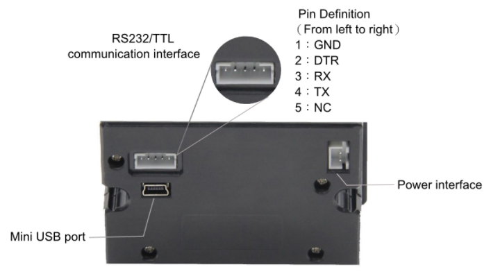
TTL通信接口
标号 |
名称 |
功能描述 |
Edge101WE 主板 UART1接口 |
|---|---|---|---|
1 |
GND |
电源地 |
GND |
2 |
DTR |
流控制 |
悬空 |
3 |
RXD |
数据接收端 |
TX |
4 |
TXD |
数据发送端 |
RX |
5 |
NC |
空脚 |
悬空 |
电源接口
标号 |
名称 |
功能描述 |
|---|---|---|
1 |
VCC |
5-9V |
2 |
GND |
电源地 |
打印机的 RX 连接UART1 接口TX,打印机TX连接UART1 接口RX,打印机 GND连接 UART1 接口GND,打印机Power interface 连接5~9V独立电源。
接线图:
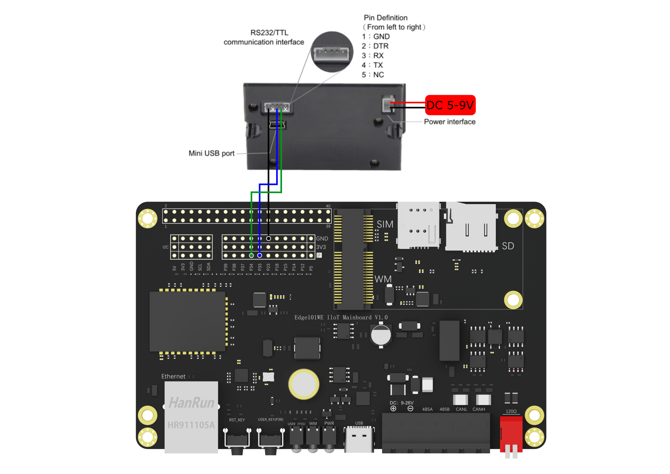
将以下例子代码烧写到主板,按下 GPIO38 板载按钮,此时可打印出 “DFRobot” 字样及其一幅条码和一幅二维码。
(参考Arduino IDE例程 Examples -> Examples for Edge101WE ->Peripherals:raw-latex:examples:raw-latex:`\thermalPrinter`)
/*!
 * @file thermalPrinter.ino
 * @brief Serial1 on the main board is connected to a thermal printer for simple printing. Here shows the printing method of bar code and two-dimensional code. For details, please see: https://www.dfrobot.com.cn/goods-1795.html
 * @copyright Copyright (c) 2010 DFRobot Co.Ltd (http://www.dfrobot.com)
 * @licence The MIT License (MIT)
 * @author [yangfeng]<feng.yang@dfrobot.com>
 * @version V1.0
 * @date 2021-09-07
 */
/*--------Print bar code instructions containing the information "DFR0503"---------*/
char bar_code[27] = {
  0x1b, 0x40,
  0x1d, 0x48, 0x02,                                                                         //General instruction 43, select the print location of the information contained in the bar code (that is, the HRI character) when printing the bar code, 0x02 means to print below the bar code
  0x1d, 0x68, 0x64,                                                                         //Set the bar code height, refer to "1 to 255", in the example set to "0x64"
  0x1d, 0x77, 0x03,                                                                         //General instruction no. 45, set horizontal width, select item 0x03 here
  0x1d, 0x78, 0x20,
  0x1d, 0x6b, 0x49, 0x09, 0x7B, 0x42, 0x44, 0x46, 0x52, 0x7B, 0x43, 0x05, 0x03              //0x09 is the length of the barcode, corresponding to DFR0503. 0x44, 0x46,0x52 are the ACILL code of the three letters DFR, 0x05, 0x03 are 0503.
};                                                                                          //If the information is DFR050308, the bar code length is 0x0B, and so on
/*--------Print the two-dimensional code instruction, which contains the information "www.dfrobot.com"---------*/
const char QRx[60] = {
  0x1b, 0x40,
  0x1d, 0x28, 0x6b, 0x03, 0x00, 0x31, 0x43, 0x05,                                             //Refer to the first special instruction set, "0x05" is the size level of the TWO-DIMENSIONAL code,
  0x1d, 0x28, 0x6b, 0x03, 0x00, 0x31, 0x45, 0x30,                                             //Set the verification level of the QR code to L
  0x1d, 0x28, 0x6b, 0x12, 0x00, 0x31, 0x50, 0x30, 0x77, 0x77, 0x77, 0x2E, 0x64, 0x66, 0x72, 0x6F, 0x62, 0x6F, 0x74, 0x2E, 0x63, 0x6F, 0x6D,
  //"0x12" is the number of characters in the QR code containing the message "www.dfrobot.com" (15 characters) plus 3.
  //“0x77,0x77,0x77,0x2E,0x64,0x66,0x72,0x6F,0x62,0x6F,0x74,0x2E,0x63,0x6F,0x6D” as characters in the url corresponding ACILL yards
  0x1b, 0x61, 0x01,                                                                           //Center the graph
  0x1d, 0x28, 0x6b, 0x03, 0x00, 0x31, 0x52, 0x30,                                             //Verify that the QR code is normal
  0x1d, 0x28, 0x6b, 0x03, 0x00, 0x31, 0x51, 0x30                                              //Print the QR code
};
const char left[3] = {0x1b,0x61,0x00};//The left
const char leftMargin[3] = {0x1b,0x42,0x02};//Indent 2 characters
bool flag = false;
void callback()
{
  flag = true;
}
void setup() {
  Serial1.begin(9600);
  pinMode(38,INPUT_PULLUP);
  attachInterrupt(digitalPinToInterrupt(38),callback,FALLING);
}
void loop() {
  if(flag){
  flag = false;
  Serial1.write(left,3);
  Serial1.println("DFRobot:");
  Serial1.write(leftMargin,3);
  Serial1.println("DRIVE THE FUTURE");
  Serial1.println("-----------------------------");
  Serial1.write(bar_code, 27);                                                             //Send instructions to printer to print bar code
  delay(5);
  Serial1.println();
  Serial1.write(QRx, 60);                                                                  //Send the command to print qr code to the printer
  Serial1.println();
  Serial1.println("-----------------------------");
  }
}
实际效果:
6.9.2 UART2 RS485通信
RS-485工业总线标准,属于半双工通信是物理层设备(串口),在两线连接下可多点双向通讯,理想状态下可挂128个设备 一般采用总线型结构连接。采用差分传输方式传输数据,通常以双绞线连接设备以达到抗共模干扰目的,距离较远时请多参考相关资料,理论最远距离1200米。
注意
应当尽量保证总线以及各区域段使用相同阻抗电缆
收发器连接总线时不要将过多收发器连线紧靠在一小段内
分支到总线的线长应当合适,不可过长
RS485通信接口我们使用到了Serial2,DE(驱动输出高电平使能)和RE(驱动输出低电平使能):GPIO16 ,RX:GPIO 36,TX:GPIO 17
API参考:
begin(unsigned long baudrate) - RS485初始化
语法
void begin(unsigned long baudrate);
void begin(unsigned long baudrate, uint32_t config);
参数
参数 |
说明 |
值范围 |
|---|---|---|
baudrate |
设置波特率 |
|
config |
默认SERIAL_8N1,可参考Serial部分的介绍 |
返回
无
end() - 禁止RS485通讯
语法
end();
参数
无
返回
无
beginTransmission() - RS485开始传输
用于启动RS485传输,需要在RS485.write(uint8_t b)前调用。
语法
RS485 .beginTransmission();
参数
无
返回
无
write(uint8_t b) - 写入到串口端口
语法
RS485.write(“A”);
参数
参数 |
说明 |
值范围 |
|---|---|---|
uint8_t b |
要写入的一个字节 |
注意:RS485库中已限制写入串口为每次一个字节。汉字占用两个字节,所以当输入一个汉字时需要调用两次该函数。
返回
返回值 |
说明 |
值范围 |
|---|---|---|
byte write() |
写入的字节数 |
endTransmission() - RS485结束传输
用于结束RS485传输,需要在RS485.write(uint8_t b)后调用。
语法
RS485 .endTransmission();
参数
无
返回
无
peek() - 监视
返回传入串行数据的下一个字节(字符),而不将其从内部串行缓冲区中删除。也就是说,对 peek() 的连续调用将返回相同的字符,下一次对 read() 的调用也将返回相同的字符。
语法
RS485.peek();
参数
无
返回
返回值 |
说明 |
值范围 |
|---|---|---|
char |
传入串行数据的第一个字节可用,如果没有数据可用,则为 -1。 |
read() - 读取串口第一个字节
语法
RS485 .read();
参数
无
返回
返回值 |
说明 |
值范围 |
|---|---|---|
char |
传入串行数据第一个字节,如果没有数据返回 -1 |
available() - 获取可从RS485端口读取的字节数
语法
RS485.available();
参数
无
返回
返回值 |
说明 |
值范围 |
|---|---|---|
int |
可供读取的字节数 |
receive() - 接收
启用接收。
语法
RS485.receive();
参数
无
返回
无
noReceive() - 接收
禁用接收。
语法
RS485.noReceive();
参数
无
返回
无
flush() - 冲洗
等待传出串行数据的传输完成。
语法
RS485.flush();
参数
无
返回
无
sendBreak(unsigned int duration) - 毫秒发送中断
以毫秒为单位发送指定持续时间的串行中断信号。
语法
RS485.sendBreak(unsigned int duration);
参数
参数 |
说明 |
值范围 |
|---|---|---|
int |
中断信号的持续时间(以毫秒为单位) |
返回
无
sendBreakMicroseconds(unsigned int duration) - 微秒发送中断
以微秒为单位发送指定持续时间的串行中断信号。
语法
RS485.sendBreakMicroseconds(unsigned int duration);
参数
参数 |
说明 |
值范围 |
|---|---|---|
int |
中断信号的持续时间(以毫秒为单位) |
返回
无
setPins(int txPin, int dePin, int rePin) - 微秒发送中断
修改用于通信的引脚。默认DE:raw-latex:RE:GPIO16 ,RX:GPIO 36,TX:GPIO 17。
语法
RS485.setPins(int txPin, int dePin, int rePin)
参数
参数 |
说明 |
值范围 |
|---|---|---|
txPin |
传输引脚(用于发送中断信号) |
|
dePin |
驱动输出使能引脚 |
|
rePin |
接收器输出使能引脚 |
返回
无
让我们先来实现一次互传,当然这是串口直接通讯
例程:RS485串口数据透传
这里使用 AccessPort 软件作为发送和接收串口信息的调试软件。
该示例为Arduino IDE例程 Examples -> Examples for Edge101WE -> ArduinoRS485:raw-latex:examples:raw-latex:`RS`485Passthrough
将代码烧录到一个主板后,通过任意USB/RS485/TTL 协议转换器发送数据给主板。
接线图:
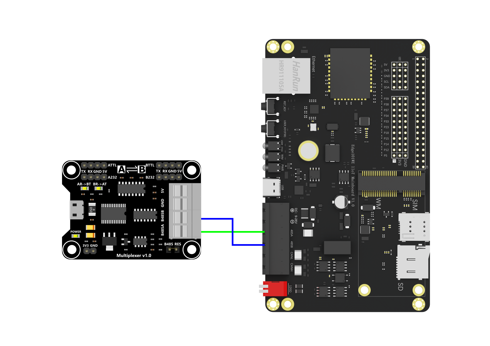
#include <ArduinoRS485.h>

RS485Class RS485;

void setup() {
  Serial.begin(9600);
  RS485.begin(9600);
}
bool flag = false;
void loop() {
  while (Serial.available()) {
    if(!flag) flag = true;
    if(flag) RS485.beginTransmission();//RS485开始传输
    RS485.write((char)Serial.read());//RS485写入到串口
  }

  if(flag) RS485.endTransmission();//RS485结束传输
  flag = false;

  while (RS485.available()) {
    Serial.write(RS485.read());
  }
}
程序将主板USB串口收到的数据通过RS485接口发送出去,同时接收RS485的数据后通过USB串口发送出去。
以下将代码烧写到主板,示例中主板的USB串口号是COM7。
在主板的RS485接口上连接一个USB/RS485/TTL 协议转换器,转换器的USB连接到电脑,此时弹出一个USB串口COM8。
从主板的USB串口COM7输入字符串 “Data sent by motherboard”,RS485转换器COM8收到发送的字符串。
RS485转换器COM8输入字符串 “Data sent by RS485 device”,主板的USB串口COM7收到发送的字符串。
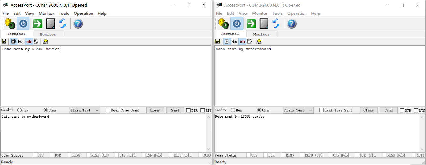
6.9.3 Modbus 协议介绍
Modbus 是一种一主多从通讯,这代表 Modbus 网络上只能有一个主站存在,主站在 Modbus 网络上没有设定地址,从站的地址范围为 0 - 247,其中 0 为广播地址像所有从机发送,从站的实际地址范围为 1 - 247。 Modbus 通信标准协议可以通过各种传输方式传播,就比如 RS485。
Modbus RTU 协议格式
Modbus RTU 可以理解为一种规定好的一种 Modbus 格式,格式最明显特点就是通过等待发送3.5个字符所需时间(通常4ms)表示这段数据结束同时表示下一段的开始。
Modbus RTU 报文格式
Modbus RTU 报文格式分为四部分,分别是设备地址,功能代码,数据,CRC校验,其中CRC校验低位在前。
设备地址 |
功能代码 |
数据格式 |
CRC校验L |
CRC校验H |
|---|---|---|---|---|
1 Byte |
1 Byte |
N*Byte |
1Byte |
1Byte |
设备地址
不同设备对应不同地址,只有主机发送地址与从机地址相符合的情况下,对应的从机才会执行相应操作。
功能代码
在确定了哪一个从机接收该信息后,此时就需要对应的功能代码来告诉从机需要做什么,以下是常用的功能代码。
Modbus 常用功能代码
0x01 |
0x02 |
0x03 |
0x04 |
|---|---|---|---|
读线圈寄存器 |
读离散输入寄存器 |
读保持寄存器 |
读输入寄存器 |
0x05 |
0x06 |
0x0f |
0x10 |
写单个线圈寄存器 |
写单个保持寄存器 |
写多个线圈寄存器 |
写多个保持寄存器 |
数据和CRC
我们根据下面的读保持寄存器示例来理解数据段会填入什么和接收什么。
举例演示不够?可以来这里看看(答案中已有人指出了文章中的唯一一处问题,也许你会在看到末尾前将其发现!)
举例演示:读URM14-RS485 精密超声波传感器保持寄存器
这里我们使用的是DFRobot的一款URM14-RS485 精密超声波传感器进行示例。
我们通过功能代码0x03读保持寄存器来进行读取测量距离值(单位:mm),测量数据从0x05寄存器地址开始,数据是一个字节的距离数据。
主机发送
信息名称 |
字节 |
发送信息 |
解释 |
|---|---|---|---|
从机地址 |
1 |
0x0C |
传感器从机地址 |
功能代码 |
1 |
0x03 |
读保持寄存器 |
寄存器起始地址 |
2 |
0x00,0x05 |
寄存器地址 |
数据长度 |
2 |
0x00,0x01 |
读取寄存器个数 |
CRC校验码 |
2 |
0x95,0x16 |
CRC校验 |
命令功能是读取地址为0x0C 的从机保持寄存器(代码0x03),0x0005 这个位置开始, 读取 1个保持寄存器,结尾是CRC校验码0x95,0x16 。
从机返回
信息名称 |
字节 |
发送信息 |
解释 |
|---|---|---|---|
从机地址 |
1 |
0x0C |
传感器从机地址 |
功能代码 |
1 |
0x03 |
读保持寄存器 |
数据字节个数 |
1 |
00x2 |
返回数据字节个数 |
数据 |
2 |
0x05,0x43 |
测量的距离数据 |
CRC校验码 |
2 |
0xD7,0x24 |
CRC校验 |
举例演示:写URM14-RS485 精密超声波传感器单个保持寄存器
通过功能代码0x06写单个保持寄存器进行模式设置,模式设置从0x08寄存器地址开始,通过输入一字节数据进行设置(相关设置请参考传感器的详细介绍)。
主机发送
信息名称 |
字节 |
发送信息 |
解释 |
|---|---|---|---|
从机地址 |
1 |
0x0C |
传感器从机地址 |
功能代码 |
1 |
0x06 |
写单个保持寄存器 |
寄存器起始地址 |
2 |
0x00,0x08 |
寄存器地址 |
数据长度 |
2 |
0x00,0x00 |
开启温度补偿并自动读取距离值 |
CRC校验码 |
2 |
0x09,0x15 |
CRC校验 |
从机返回
从机向主机返回了 0C 06 00 08 00 00 09 15,这表示了已设置 成功
注意:从机返回值根据具体传感器来确定,这个传感器返回值只是特例,有的传感器可能会全部返回 0 来表示设置成功。
API参考
coilRead() - 读取单个线圈
discreteInputRead() - 读取单个离散输入
holdingRegisterRead() - 读取单个保持寄存器
inputRegisterRead() - 读取单个输入寄存器
语法
//读取单个线圈
int coilRead(int address);
int coilRead(int id, int address);
//读取单个离散输入
int discreteInputRead(int address);
int discreteInputRead(int id, int address);
//读取单个保持寄存器
long holdingRegisterRead(int address);
long holdingRegisterRead(int id, int address);
//读取单个输入寄存器
long inputRegisterRead(int address);
long inputRegisterRead(int id, int address);
参数
参数 |
说明 |
值范围 |
|---|---|---|
id (slave) |
目标的 id,如果未指定,默认为 0x00 |
|
address |
用于操作的地址 |
返回
返回值 |
说明 |
值范围 |
|---|---|---|
int |
true:对应函数名称值false:-1 |
coilWrite() - 写入单个线圈
holdingRegisterWrite() - 写单个保持寄存器
语法
//写入单个线圈
int coilWrite(int address, uint8_t value);
int coilWrite(int id, int address, uint8_t value);
//写单个保持寄存器
int holdingRegisterWrite(int address, uint16_t value);
int holdingRegisterWrite(int id, int address, uint16_t value);
参数
参数 |
说明 |
值范围 |
|---|---|---|
id (slave) |
目标的 id,如果未指定,默认为 0x00 |
|
address |
用于操作的地址 |
|
value |
要写入的值 |
返回
返回值 |
说明 |
值范围 |
|---|---|---|
int |
true:1 false:0 |
registerMaskWrite() - 掩码写入寄存器
语法
int registerMaskWrite(int address, uint16_t andMask, uint16_t orMask);
int registerMaskWrite(int id, int address, uint16_t andMask, uint16_t orMask);
参数
参数 |
说明 |
值范围 |
|---|---|---|
id (slave) |
目标的 id,如果未指定,默认为 0x00 |
|
address |
用于操作的地址 |
|
andMask |
用于操作的AND掩码 |
|
orMask |
用于操作的 OR 掩码 |
返回
返回值 |
说明 |
值范围 |
|---|---|---|
int |
true:1 false:0 |
beginTransmission() - 开始写入多个线圈或保持寄存器的过程。
语法
int beginTransmission(int type, int address, int nb);
int beginTransmission(int id, int type, int address, int nb);
参数
参数 |
说明 |
值范围 |
|---|---|---|
id (slave) |
目标的 id,如果未指定,默认为 0x00 |
|
type |
要执行的写入类型,COILS 或 HOLD_REGISTERS |
|
address |
用于操作的地址 |
|
nb |
要写入的值的数量 |
返回
返回值 |
说明 |
值范围 |
|---|---|---|
int |
true:1 false:0 |
write() - 设置由 beginTransmission(…) 启动的写入操作的值。
语法
int write(unsigned int value);
参数
参数 |
说明 |
值范围 |
|---|---|---|
value |
要写入的值 |
返回
返回值 |
说明 |
值范围 |
|---|---|---|
int |
true:1 false:0 |
endTransmission() - 结束写入多个线圈或保持寄存器的过程。
语法
int endTransmission();
参数
无
返回
返回值 |
说明 |
值范围 |
|---|---|---|
int |
true:1 false:0 |
requestFrom() - 读取多个线圈、离散输入、保持寄存器或输入寄存器值。使用 available() 和 read() 处理读取的值
语法
int requestFrom(int type, int address, int nb);
int requestFrom(int id, int type, int address,int nb);
参数
参数 |
说明 |
值范围 |
|---|---|---|
id (slave) |
目标的 id,如果未指定,默认为 0x00 |
|
type |
要执行的读取 类型,COILS、DISCRETE_INPUTS、HOLD_REGISTERS 或 INPUT_REGISTERS |
|
address |
用于操作的起始地址 |
|
nb |
要读取的值的数量 |
返回
返回值 |
说明 |
值范围 |
|---|---|---|
int |
true:返回读取的值数false:0 |
available() - 调用 requestFrom(…) 后查询可读取的值的个数
语法
int available();
参数
无
返回
返回值 |
说明 |
值范围 |
|---|---|---|
int |
可用于读取的值数量 read() |
read() - 调用 requestFrom(…) 后读取一个值
语法
long read();
参数
无
返回
返回值 |
说明 |
值范围 |
|---|---|---|
int |
true:返回读取的值false:-1 |
lastError() - 将最后一个错误原因读取为字符串
语法
const char* lastError();
参数
无
返回
返回值 |
说明 |
值范围 |
|---|---|---|
const char |
最后一个错误原因为 C 字符串 |
end() - 停止服务器
语法
void end();
参数
无
返回
无
begin() - 使用指定参数启动Modbus RTU
语法
int begin(unsigned long baudrate, uint32_t config = SERIAL_8N1);
int begin(RS485Class& rs485, unsigned long baudrate, uint32_t config = SERIAL_8N1);
参数
参数 |
说明 |
值范围 |
|---|---|---|
baudrate |
要使用的波特率 |
|
config |
默认SERIAL_8N1,可参考Serial部分的介绍 |
|
rs485 |
设置rs485为RS485Class的引用 |
返回
返回值 |
说明 |
值范围 |
|---|---|---|
int |
true:1false:0 |
例程:读取传感器距离值数据
本例程展示了如何通过写入单个保持寄存器设置模式为自动获取,并读取保持寄存器来获得 URM14 超声波的距离值。
接线图:
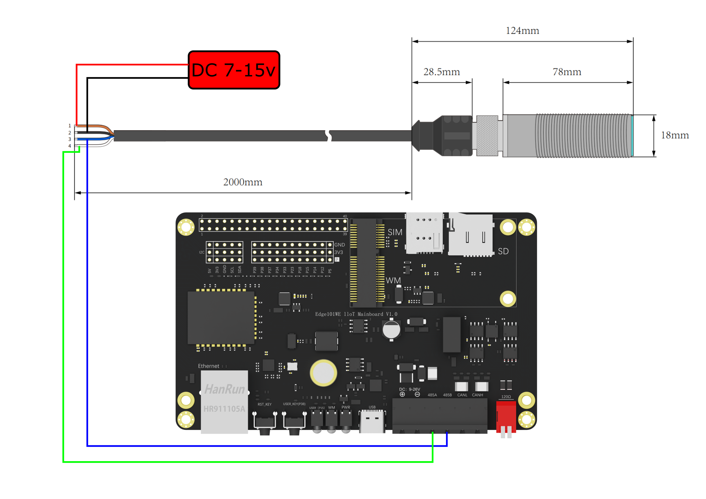
#include <ArduinoModbus.h>

RS485Class RS485;
ModbusRTUClientClass ModbusRTUClient(RS485);


//由于传感器特性我们需要进行一次设置,设置其读取距离值为自动
void Start()
{
  if (!ModbusRTUClient.holdingRegisterWrite(0x0C, 0x08, 0)){
    Serial.print("Failed to write coil! ");
    Serial.println(ModbusRTUClient.lastError());
  }else
    Serial.println("sucess!");
}

void setup() {
  Serial.begin(19200);
  while (!Serial);

  if (!ModbusRTUClient.begin(19200)) {
    Serial.println("Failed to start Modbus RTU Client!");
    while (1);
  }
  Start();
}

void loop() {

  // 读取0x0C从机,读保持寄存器,地址从0x05开始,读1个寄存器
  if (!ModbusRTUClient.requestFrom(0x0C, HOLDING_REGISTERS, 0x05, 1)) {
    Serial.print("failed to read registers! ");
    Serial.println(ModbusRTUClient.lastError());
  } else {
    // 我们读取出返回的数据
      float distance = (float)ModbusRTUClient.read();

      Serial.println(distance/10.0);
  }

  delay(1000);
}
将以上代码下载到主板中。
URM14 传感器 RS485 通信线的A和B连接到主板 RS485 的A和B,URM14 传感器电源正负极连接到外部直流12V供电。
Arduino串口终端打印出测量到的距离,单位毫米。
102.50
103.00
137.20
101.00
130.40
174.40
238.90
例程:RLY-8继电器控制
本例程通过主板的RS485接口连接 DFR0290 RLY-8-PoE-RS485 8路网络控制继电器模块,控制8路继电器的动作。
接线图:
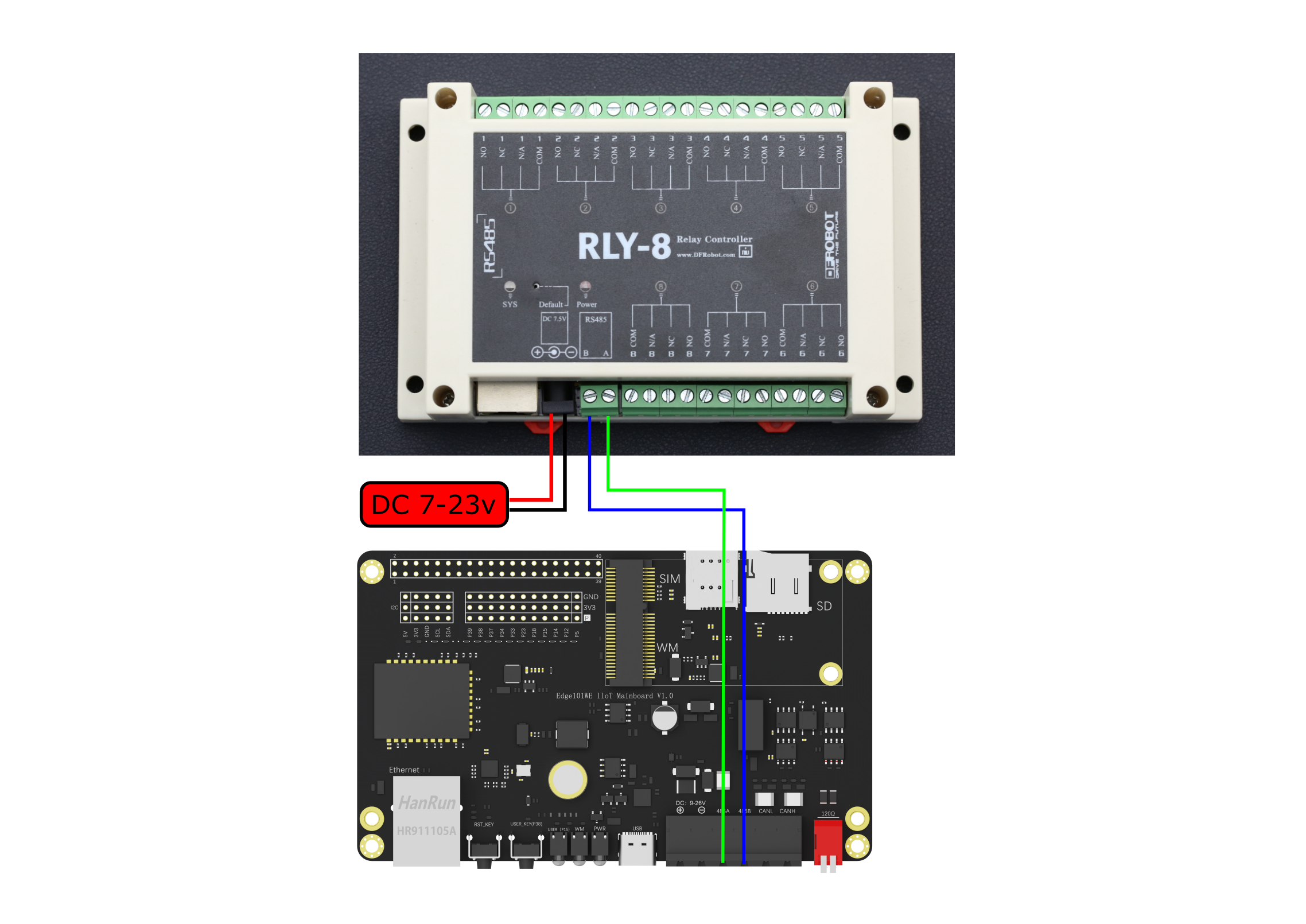
(参考Arduino IDE例程 Examples -> Examples for Edge101WE ->RTU:raw-latex:ModbusRTUClientRelay8)
/*!
 * @file ModbusRTUClientRelay8.ino
 * @brief 用ArduinoModbus库完成控制继电器通信
 * @n 依次打开RLY-8 Relay Controller的8个继电器,再按打开的顺序关闭
 * @n 实验现象为8个继电器的工作指示灯依次点亮后再顺序熄灭
 * @copyright   Copyright (c) 2010 DFRobot Co.Ltd (http://www.dfrobot.com)
 * @licence     The MIT License (MIT)
 * @author [qsj](qsj.huang@dfrobot.com)
 * @version  V0.1
 * @date  2021-06-21
 */
#include <ArduinoModbus.h>
#include <ArduinoRS485.h>

RS485Class RS485;
ModbusRTUClientClass ModbusRTUClient(RS485);

#define   SLAVE_ADDR                ((uint16_t)0x01)
uint16_t relayNumber = 0;

/*
 *@brief Read data from holding register of client
 *
 *@param addr : Address of Client
 *@param reg: Reg index
 *@return data if execute successfully, false oxffff.
 */
uint16_t readData(uint16_t addr, uint16_t reg)
{
  uint16_t data;
  if (!ModbusRTUClient.requestFrom(addr, HOLDING_REGISTERS, reg, 1)){
    Serial.print("failed to read registers! ");
    Serial.println(ModbusRTUClient.lastError());
    data = 0xffff;
  }else{
    data =  ModbusRTUClient.read();
  }
  return data;
}

/*
 *@brief write data to holding register of client
 *
 *@param addr : Address of Client
 *@param reg: Reg index
 *@param data: The data to be written
 *@return 1 if execute successfully, false 0.
 */
uint16_t writeData(uint16_t addr, uint16_t reg, uint16_t data)
{
  if (!ModbusRTUClient.coilWrite(addr, reg, data)){
    Serial.print("Failed to write coil! ");
    Serial.println(ModbusRTUClient.lastError());
    return 0;
  }else
    return 1;
}

void setup() {
  Serial.begin(9600);
  ModbusRTUClient.begin(9600);
}

void loop() {
  // 依次接通8个继电器,现象为8个继电器工作指示灯依次点亮
  for(relayNumber=0; relayNumber<8; relayNumber++){
    writeData(SLAVE_ADDR, relayNumber, 1);
    delay(500);
  }
  // 依次断开8个继电器,现象为8个继电器工作指示灯依次熄灭
  for(relayNumber=0; relayNumber<8; relayNumber++){
    writeData(SLAVE_ADDR, relayNumber, 0);
    delay(500);
  }
}
6.10 I2C驱动程序
I2C 是一种串行同步半双工式通信协议,总线上可以同时挂载多个主机和从机。I2C 总线由串行数据线 (SDA) 线和串行时钟线 (SCL) 线构成。这些线都需要上拉电阻。
I2C 具有简单且制造成本低廉等优点,主要用于低速外围设备的短距离通信(一英尺以内)。
Edge101WE 主板有两个 I2C 控制器(也称为端口),负责处理在 I2C 两根总线上的通信。每个控制器都可以设置为主机或从机。例如,可以同时让一个控制器用作主机,另一个用作从机。或者两个控制器都作为主机读取地址一样的两个从机设备。
主板扩展接口使用GPIO18 作为I2C SDA,GPIO 23 作为 I2C SCL。 主板使用和Arduino Wire兼容的库。
注意
I2C地址有7位和8位版本。7位标识设备,第八位确定是正在写入设备还是从中读取设备。Wire库始终使用7位地址。如果您有一个使用8位地址的数据表或示例代码,则需要删除低位(即,将值向右移一位),从而得到0到127之间的地址。但是,地址从0到7未使用,因为保留了它们,因此可以使用的第一个地址是8。请注意,连接SDA / SCL引脚时需要一个上拉电阻。
Wire库的实现使用32字节的缓冲区,因此任何通信都应在此限制之内。单次传输中超出的字节将被丢弃。
6.10.1 I2C (主机)
I2C需要引入自带库 Wire.h Wire继承steam类 steam类有的他都有。
#include "Wire.h"
API参考
begin() - 初始化I2C (以主机身份)
启动Wire库,并以主机或从机的身份加入I2C总线。通常应该只调用一次。
语法
Wire.begin();
Wire.begin(pinSDA, pinSCL);
Wire.begin(pinSDA, pinSCL, frequency);
参数
传入值 |
说明 |
值范围 |
|---|---|---|
Wire |
I2C端口对象 |
|
pinSDA |
I2C SDA使用的GPIO号 |
|
pinSCL |
I2C SCL使用的GPIO号 |
|
frequency |
I2C时钟频率(默认值为400000) |
100000,400000 |
返回
无
Wire.setClock() - 修改I2C通信的时钟频率
此功能修改I2C通信的时钟频率。 I2C从设备没有最低工作时钟频率,但是通常以100KHz为基准。
语法
Wire.setClock(clockFrequency);
参数
传入值 |
说明 |
值 范 围 |
|---|---|---|
Wire |
I2C端口对象 |
|
clock Frequency |
所需通信时钟的 值(以赫兹为单位)。可接受的值为100000(标准模式) 和400000(快速模式)。一些处理器还支持10000(低速模 式),1000000(加快速模式)和3400000(高速模式)。 |
返回
无
requestFrom() - 以主机身份向从机请求数据
语法
void requestFrom(uint16_t address, uint8_t quantity, bool stop)
请求完成后 主机可以用 Wire.available()和Wire.read()等函数等待并获取从机的回答。
Wire.requestFrom(address, quantity);
Wire.requestFrom(address, quantity, stop);
参数
传入值 |
说明 |
值 范 围 |
|---|---|---|
Wire |
I2C端口对象 |
|
uint16_t address |
要发送到的从机设备的7位地址 |
|
uint8_t quantity |
请求字节数 |
|
bool stop |
是否发送停止 , 如果为true(默认值), 在 请求之后发送停止消息,以释放I2C总线。如果为false, 发送一个重新开始的信息, 并继续保持I2C总线的连接。 这样一来,一台主设备就可以在控制下发送多个请求。 |
返回
无
beginTransmission() - 主机开始传输
void beginTransmission(int address)
使用给定地址开始向I2C从设备的传输。随后, 主机可以使用Wire.write() 写数据,并使用Wire.endTransmission() 结束传输。
语法
Wire.beginTransmission(120);
参数
传入值 |
说明 |
值范围 |
|---|---|---|
Wire |
I2C端口对象 |
|
int address |
要发送到的从机设备的7位地址 |
返回
无
endTransmission() - 结束数据传输
结束传输, 并释放I2C总线。
语法
Wire.endTransmission();
Wire.endTransmission(stop);
参数
传 入 值 |
说明 |
值 范 围 |
|---|---|---|
W ire |
I2C端口对象 |
|
s top |
如果为 true(默认值),则endTransmission()在发送后发送停止消息 ,释放I2C总线。如果为false,则endTransmission()在传输后 发送重启消息。总线不会释放,这阻止了另一个主设备在消息之 间传输。这样一来,一台主设备就可以在控制下发送多个传输。 |
返回
返回值 |
说明 |
值范围 |
|---|---|---|
byte |
操作结果 |
0 成功1 数据过长,超出发送缓冲区2 在地址发送时接收到NACK信号3 在数据发送时接收到NACK信号4 其他错误 |
write() - 写数据
当作为主机时: 主机将要发送的数据加入发送队列。 当作为从机时: 从机发送的数据给主机。
语法
Wire.write(value); //单字节发送
Wire.write(string); //以一系列字节发送
Wire.write(data,length); //以字节形式发送,指定长度
参数
传入值 |
说明 |
值范围 |
|---|---|---|
Wire |
I2C端口对象 |
|
value |
要作为单个字节发送的值 |
|
string |
以一系列字节发送的字符串 |
|
data |
以字节为单位发送的数据数组 |
|
length |
要传输的字节数 |
返回
返回值 |
说明 |
值范围 |
|---|---|---|
byte |
可读字节数 |
例程
#include <Wire.h>

byte val = 0;

void setup()
{
  Wire.begin(); // join i2c bus
}

void loop()
{
  Wire.beginTransmission(44); // transmit to device #44 (0x2c)
                              // device address is specified in datasheet
  Wire.write(val);             // sends value byte
  Wire.endTransmission();     // stop transmitting

  val++;        // increment value
  if(val == 64) // if reached 64th position (max)
  {
    val = 0;    // start over from lowest value
  }
  delay(500);
}
available() - 接收数据寄存器有值
返回接收到的字节数
语法
Wire.available();
参数
传入值 |
说明 |
值范围 |
|---|---|---|
Wire |
I2C端口对象 |
返回
返回值 |
说明 |
值范围 |
|---|---|---|
byte |
可读字节数 |
read() - 读取1byte数据
当作为主机时: 主机使用requestFrom()后 要使用此函数获取数据。 当作为从机时: 从机读取主机给的数据。
语法
Wire.read();
参数
传入值 |
说明 |
值范围 |
|---|---|---|
Wire |
I2C端口对象 |
返回
返回值 |
说明 |
值范围 |
|---|---|---|
byte |
读到的字节数据 |
例程
#include <Wire.h>

void setup()
{
  Wire.begin();        // join i2c bus (address optional for master)
  Serial.begin(9600);  // start serial for output
}

void loop()
{
  Wire.requestFrom(2, 6);    // request 6 bytes from slave device #2

  while(Wire.available())    // slave may send less than requested
  {
    char c = Wire.read();    // receive a byte as character
    Serial.print(c);         // print the character
  }

  delay(500);
}
readBytes() - 读取多个字节的数据
size_t readBytes(char *buffer, size_t length)
语法
Wire.readBytes();
参数
传入值 |
说明 |
值范围 |
|---|---|---|
Wire |
I2C端口对象 |
|
buffer |
||
length |
返回
返回值 |
说明 |
值范围 |
|---|---|---|
byte |
数据长度 |
readBytesUntil() - 读取直到遇到某字符
size_t readBytesUntil(char terminator, char *buffer, size_t length)
语法
Wire.readBytesUntil();
参数
传入值 |
说明 |
值范围 |
|---|---|---|
Wire |
I2C端口对象 |
|
char terminator |
终结字符 char类型 |
|
char *buffer |
接收缓冲区, 一个char型指针 |
|
size_t length |
数据长度 |
返回
返回值 |
说明 |
值范围 |
|---|---|---|
byte |
数据长度 |
busy() - 查询当前I2C是否忙线中
语法
Wire.busy();
参数
传入值 |
说明 |
值范围 |
|---|---|---|
Wire |
I2C端口对象 |
返回
返回值 |
说明 |
值范围 |
|---|---|---|
bool |
数据长度 |
其他Stream类的方法 可参考串口部分的介绍
readString() - 读取字符串
readStringUntil() - 将来自缓冲区的字符读取到数组中
parseInt() - 从流中查找第一个有效的整型数据
parseFloat() - 从缓冲区返回第一个有效的float型数据。
find() - 从缓冲区读取数据,直到读取到指定的字符串
findUntil() - 从缓冲区读取数据,直到读取到指定的字符串或指定的停止符
setTimeout() - 设置超时时间
6.10.2 I2C从机模式
从机有些函数和主机是一样的, 请看主机部分说明。
API参考
begin(adress) - 初始化I2C (以从机身份)
语法
Wire.begin(address); //address取值0~127
参数
传入值 |
说明 |
值范围 |
|---|---|---|
Wire |
I2C端口对象 |
|
address |
从机地址 |
0 ~ 127 |
返回
无
onReceive() - 当从机收到数据时触发函数
void onReceive(void (*)(int))
语法
Wire.onReceive();
参数
传入值 |
说明 |
值范围 |
|---|---|---|
Wire |
I2C端口对象 |
|
void (*)(int) |
回调函数 (接收一个int类型的参数,代表接收的字节数) |
返回
无
主设备与从设备通信 在此示例中,将两个板编程为通过I2C协议在主读取器与从发送器配置中相互通信。Arduino的Wire Library的几个功能用于完成此任务。主设备每半秒向唯一寻址的从设备发送6个字节的数据。收到该消息后,就可以在运行从设备的串行监视器窗口中查看该消息。
每个从设备必须具有其自己的唯一地址,并且主设备和从设备都需要轮流通过同一条数据线进行通信。这样,您的Arduino开发板就有可能仅使用微控制器的两个引脚(使用每个设备的唯一地址)与许多设备或其他开发板进行通信。
主机例程
// Wire Master Writer
// by Nicholas Zambetti <http://www.zambetti.com>

// Demonstrates use of the Wire library
// Writes data to an I2C/TWI slave device
// Refer to the "Wire Slave Receiver" example for use with this

// Created 29 March 2006

// This example code is in the public domain.


#include <Wire.h>

void setup()
{
  Wire.begin(); // join i2c bus (address optional for master)
}

byte x = 0;

void loop()
{
  Wire.beginTransmission(4); // transmit to device #4
  Wire.write("x is ");        // sends five bytes
  Wire.write(x);              // sends one byte
  Wire.endTransmission();    // stop transmitting

  x++;
  delay(500);
}
从机例程
// Wire Slave Receiver
// by Nicholas Zambetti <http://www.zambetti.com>

// Demonstrates use of the Wire library
// Receives data as an I2C/TWI slave device
// Refer to the "Wire Master Writer" example for use with this

// Created 29 March 2006

// This example code is in the public domain.


#include <Wire.h>

void setup()
{
  Wire.begin((uint8_t)0x04);                // join i2c bus with address #4
  Wire.onReceive(receiveEvent); // register event
  Serial.begin(9600);           // start serial for output
}

void loop()
{
  delay(100);
}

// function that executes whenever data is received from master
// this function is registered as an event, see setup()
void receiveEvent(int howMany)
{
  while(1 < Wire.available()) // loop through all but the last
  {
    char c = Wire.read(); // receive byte as a character
    Serial.print(c);         // print the character
  }
  int x = Wire.read();    // receive byte as an integer
  Serial.println(x);         // print the integer
}
onRequest() - 当从机被请求时触发函数
void onRequest(void (*)())
语法
Wire.onRequest(requestEvent);
参数
传入值 |
说明 |
值范围 |
|---|---|---|
Wire |
I2C端口对象 |
|
void (*)() |
回调函数 |
返回
无
主设备与从设备通信
在某些情况下,多个主板彼此共享信息可以使用I2C总线方式。在此示例中,将两个主板编程为通过I2C协议在主读取器/从发送器配置中相互通信。Wire Library的几个功能用于完成此任务。主设备请求并读取从唯一寻址的从设备发送来的6字节数据。收到该消息后,便可以在串行监视器窗口中对其进行查看。
主设备例程
// Wire Master Reader
// by Nicholas Zambetti <http://www.zambetti.com>

// Demonstrates use of the Wire library
// Reads data from an I2C/TWI slave device
// Refer to the "Wire Slave Sender" example for use with this

// Created 29 March 2006

// This example code is in the public domain.


#include <Wire.h>

void setup() {
  Wire.begin();        // join i2c bus (address optional for master)
  Serial.begin(9600);  // start serial for output
}

void loop() {
  Wire.requestFrom(8, 6);    // request 6 bytes from slave device #8

  while (Wire.available()) { // slave may send less than requested
    char c = Wire.read(); // receive a byte as character
    Serial.print(c);         // print the character
  }

  delay(500);
}
从设备例程
// Wire Slave Sender
// by Nicholas Zambetti <http://www.zambetti.com>

// Demonstrates use of the Wire library
// Sends data as an I2C/TWI slave device
// Refer to the "Wire Master Reader" example for use with this

// Created 29 March 2006

// This example code is in the public domain.


#include <Wire.h>

void setup() {
  Wire.begin((uint8_t)0x08);                 // join i2c bus with address #8
  Wire.onRequest(requestEvent); // register event
}

void loop() {
  delay(100);
}

// function that executes whenever data is requested by master
// this function is registered as an event, see setup()
void requestEvent() {
  Wire.write("hello "); // respond with message of 6 bytes
  // as expected by master
}
例程:扫描I2C总线上连接的设备
例程每隔5秒扫描I2C总线上的设备,并将扫描到的从机设备地址从串口打印出来。
(参考Arduino IDE例程 Examples -> Examples for Edge101WE ->Wire:raw-latex:examples:raw-latex:`\WireScan`)
#include "Wire.h"

void setup() {
  Serial.begin(115200);
  Wire.begin();
}

void loop() {
  byte error, address;
  int nDevices = 0;

  delay(5000);

  Serial.println("Scanning for I2C devices ...");
  for(address = 0x01; address < 0x7f; address++){
    Wire.beginTransmission(address);
    error = Wire.endTransmission();
    if (error == 0){
      Serial.printf("I2C device found at address 0x%02X\n", address);
      nDevices++;
    } else if(error != 2){
      Serial.printf("Error %d at address 0x%02X\n", error, address);
    }
  }
  if (nDevices == 0){
    Serial.println("No I2C devices found");
  }
}
串口打印出扫描到的设备,0x51地址是主板上RTC芯片的I2C地址。
Scanning for I2C devices ...
I2C device found at address 0x51
Scanning for I2C devices ...
I2C device found at address 0x51
例程:读取板载RTC时钟
设置时间和读取时间
(参考Arduino IDE例程 Examples -> Examples for Edge101WE ->RTC:raw-latex:setClock)
/*!
 * @file setClock.ino
 * @brief Demonstration of Rtc_Pcf8563 Set Time. Set the clock to a time then loop over reading time and output the time and date to the serial console.
 * @copyright   Copyright (c) 2010 DFRobot Co.Ltd (http://www.dfrobot.com)
 * @licence     The MIT License (MIT)
 * @maintainers [Fary](feng.yang@dfrobot.com)
 * @version  V1.0
 * @date  2022-1-12
 */
#include "PCF8563T.h"

//init the real time clock
PCF8563T rtc;

void setup()
{
  //clear out the registers
  rtc.initClock();
  //set a time to start with.
  //day, weekday, month, century(1=1900, 0=2000), year(0-99)
  rtc.setDate(/*day=*/25, /*weekday=*/2, /*month=*/1, /*century*/0, /*year*/22);
  //hr, min, sec
  rtc.setTime(/*hour=*/16, /*minute=*/4, /*sec=*/40);
  Serial.begin(115200);
}

void loop()
{
  //both format functions call the internal getTime() so that the
  //formatted strings are at the current time/date.
  Serial.println(rtc.formatTime());
  Serial.println(rtc.formatDate());
  delay(1000);
}
串口打印出每秒更新的实时时间
16:04:40
01/25/2022
16:04:41
01/25/2022
16:04:42
01/25/2022
例程:通过WiFi获取NTP网络时间
#include "PCF8563T.h"
#include <WiFi.h>
#include "time.h"

//init the real time clock
PCF8563T rtc;

const char* ssid ="your_ssid";//wlan information
const char* password = "your_password";
const char* ntpServer = "pool.ntp.org";
const long gmtOffset_sec=8*3600;
const int daylightOffset_sec = 0;

int getTimeFromNTP()
{
    struct tm timeinfo;
    bool century = true;
    int8_t year = 0;
    if(!getLocalTime(&timeinfo)){
      Serial.println("Failed to obtian time");
      return -1;
    }
    if(timeinfo.tm_year>100){
        century = false;
        year = timeinfo.tm_year -100;
    }
    rtc.setDateTime(timeinfo.tm_mday,timeinfo.tm_wday,timeinfo.tm_mon+1,century,year,
                timeinfo.tm_hour,timeinfo.tm_min,timeinfo.tm_sec);
    return 0;
}

void setup()
{
  Serial.begin(115200);
  Serial.printf("Connecting to %s",ssid);
  WiFi.begin(ssid,password);
  while(WiFi.status()!=WL_CONNECTED){
    delay(500);
    Serial.print(".");
  }
  Serial.println(" CONNECTED");
  configTime(gmtOffset_sec, daylightOffset_sec, ntpServer);
  rtc.initClock();
  while(getTimeFromNTP()!=0);
}
void loop(){
  Serial.println(rtc.formatTime());
  Serial.println(rtc.formatDate());
  delay(1000);
}
例程:在Gravity接口扩展8位LED数码管显示器
在主板的I2C接口连接一个 DFR0646 Gravity: 8位数码管显示模块,通过模块显示字符、整数或小数。
接线图:
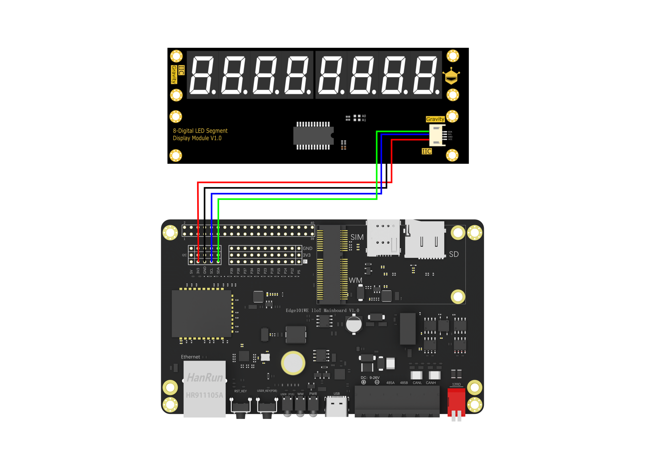
/*!
 * @file led8Print.ino
 *
 * @copyright   Copyright (c) 2010 DFRobot Co.Ltd (http://www.dfrobot.com)
 * @licence     The MIT License (MIT)
 * @author [Actor](liang.li@dfrobot.com)
 * @version  V1.0
 * @eGPAte  2019-12-10
 * @get from https://www.dfrobot.com
 * @url https://github.com/DFRobot/DFRobot_LedDisplayModule
 */
# include "DFRobot_LedDisplayModule.h"

DFRobot_LedDisplayModule LED(Wire, 0xE0);

void setup()
{
  Serial.begin(115200);
  /*wait for the chip to be initialized completely, and then exit*/
  while(LED.begin8() != 0)
  {
    Serial.println("Initialization of the chip failed, please confirm that the chip connection is correct!");
    delay(1000);
  }
}

void loop()
{
  LED.setDisplayArea8(3,4,5,6);
  LED.print8("H","A","L","O");
  delay(1000);

  LED.setDisplayArea8(3,4,5,6,7);
  LED.print8("8","-","L","E","D");
  delay(1000);
}
6.11 SPI驱动程序
Edge101WE 主板有一个SPI接口用于连接外置的SD存储卡或LCD显示器。
注意:主板SD卡槽和Gravity SPI接口是共用的同一个SPI接口,不能同时连接两个设备。
Arduino SPI 库允许您使用作为主设备与 SPI 设备进行通信。
要使用此库需要增加 # include < spi.h >
串行外围设备接口(SPI)是微控制器使用的同步串行数据协议,用于在短距离内快速与一个或多个外围设备进行通信。它也可以用于两个微控制器之间的通信。
使用SPI时,总是有一个主设备(通常是一个微控制器)来控制外围设备。通常这些设备有三条共同的连线:
MISO(Master In Slave Out)-从设备线路,用于从设备将数据发送到主设备
MOSI(Master Out Slave In)-主设备线路,用于主设备向从设备发送数据
SCK(串行时钟)-主设备生成的时钟脉冲,用于同步数据传输
及其每个外设需要一个SS外设选择线:
外设选择线(Slave Select),指定要联机的外设,此线输入0,代表选取,1代表未选取。这条线也称为CS(Chip Select,芯片选择线或简称片选)。分配给所有的设备,用于enable/disable指定的设备,同时用于避免由于线路忙导致的错误传输。这使您可以让多个SPI器件共享相同的MISO,MOSI和CLK线。
要为新的SPI设备编写代码,您需要注意以下几点:
您的设备可以使用的最大SPI速度是多少?
这由SPISettings中的第一个参数控制。如果您使用的芯片的额定频率为15 MHz,则使用15000000。Arduino将自动使用等于或小于SPISettings的数字的最佳速度。 数据首先移入最高有效位(MSB)还是最低有效位(LSB)?
这由第二个SPISettings参数(MSBFIRST或LSBFIRST)控制。大多数SPI芯片使用MSB优先数据顺序。 数据时钟为高电平还是低电平时是空闲的吗?采样是在时钟脉冲的上升沿还是下降沿上?
这些模式由SPISettings中的第三个参数控制。 SPI标准是宽松的,每个设备在实现上都略有不同。这意味着编写代码时必须特别注意设备的数据表。
一般来说,有四种传输方式。这些模式控制数据是否在数据时钟信号的上升沿或下降沿移入和移出(称为时钟相位),以及在高电平或低电平时时钟空闲(称为时钟极性)。四种模式根据此表将极性和相位组合在一起:
模式 |
时钟极性(CPOL) |
时钟相位(CPHA) |
输出边沿 |
数据捕捉 |
|---|---|---|---|---|
SPI_MODE0 |
0 |
0 |
下降沿 |
上升沿 |
SPI_MODE1 |
0 |
1 |
上升沿 |
下降沿 |
SPI_MODE2 |
1 |
0 |
上升沿 |
下降沿 |
SPI_MODE3 |
1 |
1 |
下降沿 |
上升沿 |
有了SPI参数后,请使用SPI.beginTransaction()开始使用SPI端口。SPI端口将使用所有设置进行配置。使用SPISettings的最简单,最有效的方法是直接在SPI.beginTransaction()内部。
例如:
SPI.beginTransaction(SPISettings(14000000, MSBFIRST, SPI_MODE0));
如果其他库通过中断使用SPI,则将阻止它们访问SPI,直到您调用SPI.endTransaction()。SPI设置在事务开始时应用,并且SPI.endTransaction() 不会更改SPI设置。除非您或某些库再次调用beginTransaction ,否则将保持该设置。SPI.endTransaction()如果您的程序与其他使用SPI的库一起使用,则应尝试最大程度地缩短调用之间的时间,以实现最佳兼容性。
之后SPI.beginTransaction(),对于大多数SPI器件,您将从机选择引脚写为LOW,调用SPI.transfer()任意次以传输数据,然后将SS引脚写为HIGH,最后调用SPI.endTransaction()。
API参考
SPI.beginTransaction() - SPI设置
该SPISettings对象用于为您的SPI设备配置SPI端口。所有这三个参数都组合到单个SPISettings对象中,该对象已提供给SPI.beginTransaction()。
当所有的设置为常数,SPISettings应直接在SPI.beginTransaction使用()。请参见下面的语法部分。对于常量,此语法可导致代码更小,更快。
如果您的任何设置都是变量,则可以创建一个SPISettings对象以保存这3个设置。然后,可以将对象名称命名为SPI.beginTransaction()。当您的设置不是常量时,创建命名的SPISettings对象可能会更有效,尤其是如果最大速度是计算或配置的变量。
语法
SPI.beginTransaction(SPISettings(14000000,MSBFIRST,SPI_MODE0))
注意: 当任何设置为变量时最佳
参数
传 入 值 |
说明 |
值范围 |
|---|---|---|
spe edM axi mum |
最大通讯速度。默认频率1 000 000,对于额定频率高达20 MHz的SPI芯片,请使用20 000 000 |
|
dat aOr der |
数据顺序 |
MSBFIRST(默认值)、LSBFIRST |
da taM ode |
数据传输模式 |
SP I_MODE0(默认值,SCLK闲置为0, SCLK上升沿采样),SP I_MODE1,SPI_MODE2、SPI_MODE3 |
返回
无
SPI.begin() - SPI初始化
语法
SPI.begin();
SPI接口默认频率1 000 000, 数据默认采用MSBFIRST(低有效位优先), 时钟模式:SPI_MODE0(SCLK闲置为0, SCLK上升沿采样)
参数
无
返回
无
SPI.setBitOrder(bitOrder) - 设置数据在SPI上的传输方式
语法
SPI.setBitOrder(LSBFIRST);
参数
传入值 |
说明 |
值范围 |
|---|---|---|
bitOrder |
传输方式, 可选: LSBFIRST 低有效位先传 ; HSBFIRST 高有效位先传 |
返回
无
SPI.setFrequency(freq) - 设置SPI频率
语法
SPI.setFrequency(1000000);
参数
传入值 |
说明 |
值范围 |
|---|---|---|
freq |
频率 |
返回
无
SPI.setDataMode(dataMode) - 设置SPI的时钟模式
语法
SPI.setDataMode(SPI_MODE0) ;
参数
传 入值 |
说明 |
值范围 |
|---|---|---|
data Mode |
时钟 模式 |
SPI_MODE0 SCLK闲置为低电平,上升沿采样(默认)SPI_MODE1 SCLK闲置为低电平,下降沿采样SPI_MODE2 SCLK闲置为高电平,上升沿采样SPI_MODE3 SCLK闲置为高电平,下降沿采样 |
返回
无
SPI.beginTransaction(setting) - 按照setting的设置启动SPI通信
采用该函数,可以代替上面三个函数。
语法
SPI.beginTransaction(setting1);
参数
传 入 值 |
说明 |
值 范 围 |
|---|---|---|
s ett ing |
SPISettings类型的对象, 有_bitOrder ,_clock ,_dataMode 这三个属性. setting1._bitOrder = LSBFIRST; setting1._clock = 1000000; setting1._dataMode = SPI_MODE0; |
返回
无
SPI.endTransaction() - 结束SPI通信
语法
SPI.endTransaction();
参数
无
返回
无
SPI.transfer(data) - 接收/发送一个字节的数据
语法
uint8_t SPIClass::transfer(uint8_t data)
SPI.transfer(0x01);
SPI.transfer16(0x0102);
SPI.transfer32(0x01020304);

uint8_t byte1;
uint16_t bytes2;
uint32_t bytes3;
byte1 = SPI.transfer();
bytes2 = SPI.transfer16();
bytes3 = SPI.transfer32();
参数
传入值 |
说明 |
值范围 |
|---|---|---|
data |
要发送的数据 |
返值
返回值 |
说明 |
值范围 |
|---|---|---|
uint8_t byte1; uint16_t bytes2; uint32_t bytes3; |
接收到的数据 |
例程:SPI TFT液晶UI控件
例程在 Edge101WE 主板的SPI接口上连接一个DFR0664的2.0寸TFT液晶屏,液晶屏驱动是 ST7789。
首先我们需要安装 DFRobot_GDL 库,然后打开 DFRobot_GDL->example->Basic->UI_bar例程
根据液晶实际连接的引脚修改例程中的引脚定义。(注意:液晶屏需要5V供电)
#elif defined(ESP32) || defined(ESP8266)
// 液晶VCC连接到 Edge101WE 主板的 +5V(40PIN扩展接口的PIN2)
// 液晶GND连接到 Edge101WE 主板的 GND
// 液晶CK 连接到 Edge101WE 主板SPI接口的 SCK
// 液晶SI 连接到 Edge101WE 主板SPI接口的 SDO
// 液晶SO 连接到 Edge101WE 主板SPI接口的 SDI
// 液晶BL 连接到 Edge101WE 主板的 3V3
// 液晶DC 连接到 Edge101WE 主板的GPIO 15
// 液晶CS 连接到 Edge101WE 主板的GPIO 5
// 液晶RT 连接到 Edge101WE 主板的GPIO 33
#define TFT_DC  15
#define TFT_CS  5
#define TFT_RST 33
接线图:
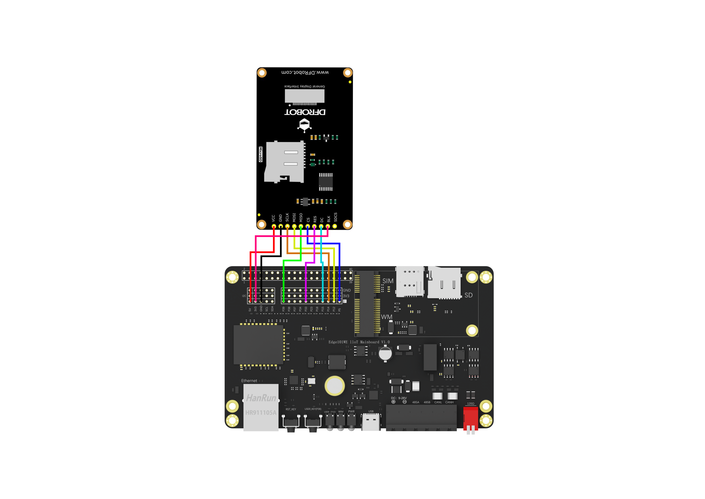
开启液晶屏幕的选择语句
DFRobot_ST7789_240x320_HW_SPI screen(/*dc=*/TFT_DC,/*cs=*/TFT_CS,/*rst=*/TFT_RST);
然后将代码下载到主板中。
这是一个加载控件的显示示例,显示了三种不同的加载控件
/*!
 * @file UI_bar.ino
 * @brief Create a progress bar control on the screen.
 * @n Users can customize the parameters of the progress bar or use the default parameters.
 * @n Users can control the value of the progress bar through the callback function of the progress bar.
 * @n The example supports Arduino Uno, Leonardo, Mega2560, FireBeetle-ESP32, FireBeetle-ESP8266, FireBeetle-M0.
 * @copyright  Copyright (c) 2010 DFRobot Co.Ltd (http://www.dfrobot.com)
 * @licence     The MIT License (MIT)
 * @author [fengli](li.feng@dfrobot.com)
 * @version  V1.0
 * @date  2019-12-6
 * @get from https://www.dfrobot.com
 * @url https://github.com/DFRobot/DFRobot_GDL/src/DFRpbot_UI
*/


#include "DFRobot_UI.h"
 #include "DFRobot_GDL.h"

/*M0*/
#if defined ARDUINO_SAM_ZERO
#define TFT_DC  7
#define TFT_CS  5
#define TFT_RST 6
/*ESP32 and ESP8266*/
#elif defined(ESP32) || defined(ESP8266)
// 液晶VCC连接到 Edge101WE 主板的 +5V(40PIN扩展接口的PIN2)
// 液晶GND连接到 Edge101WE 主板的 GND
// 液晶CK 连接到 Edge101WE 主板SPI接口的 SCK
// 液晶SI 连接到 Edge101WE 主板SPI接口的 SDO
// 液晶SO 连接到 Edge101WE 主板SPI接口的 SDI
// 液晶BL 连接到 Edge101WE 主板的 3V3
// 液晶DC 连接到 Edge101WE 主板的GPIO 15
// 液晶CS 连接到 Edge101WE 主板的GPIO 5
// 液晶RT 连接到 Edge101WE 主板的GPIO 33
#define TFT_DC  15
#define TFT_CS  5
#define TFT_RST 33
/*AVR series mainboard*/
#else
#define TFT_DC  2
#define TFT_CS  3
#define TFT_RST 4
#endif

/**
 * @brief Constructor  Constructors for hardware SPI communication
 * @param dc  Command pin or data line pin of SPI communication
 * @param cs  Chip select pin for SPI communication
 * @param rst Reset pin of the screen
 * @param bl  Screen backlight pin
 */
//DFRobot_ST7789_240x240_HW_SPI screen(/*dc=*/TFT_DC,/*cs=*/TFT_CS,/*rst=*/TFT_RST);
DFRobot_ST7789_240x320_HW_SPI screen(/*dc=*/TFT_DC,/*cs=*/TFT_CS,/*rst=*/TFT_RST);
//DFRobot_ILI9341_240x320_HW_SPI  screen(/*dc=*/TFT_DC,/*cs=*/TFT_CS,/*rst=*/TFT_RST);
//DFRobot_ILI9488_320x480_HW_SPI screen(/*dc=*/TFT_DC,/*cs=*/TFT_CS,/*rst=*/TFT_RST);
/* M0 mainboard DMA transfer */
//DFRobot_ST7789_240x240_DMA_SPI screen(/*dc=*/TFT_DC,/*cs=*/TFT_CS,/*rst=*/TFT_RST);
//DFRobot_ST7789_240x320_DMA_SPI screen(/*dc=*/TFT_DC,/*cs=*/TFT_CS,/*rst=*/TFT_RST);
//DFRobot_ILI9341_240x320_DMA_SPI screen(/*dc=*/TFT_DC,/*cs=*/TFT_CS,/*rst=*/TFT_RST);
//DFRobot_ILI9488_320x480_DMA_SPI screen(/*dc=*/TFT_DC,/*cs=*/TFT_CS,/*rst=*/TFT_RST);


/**
 * @brief Construct a function
 * @param gdl Screen object
 * @param touch Touch object
 */
DFRobot_UI ui(&screen, NULL);


uint8_t value1 = 0;
uint8_t value2 = 0;
uint8_t value3 = 0;
//Callback function of progress bar1
void barCallback1(DFRobot_UI:: sBar_t &obj){
    //Enable the progress bar plus 1 in each time, it enters the callback function.
   delay(50);
    obj.setValue(value1);
    if(value1 < 100) value1++;
}
//Callback function of progress bar2
void barCallback2(DFRobot_UI:: sBar_t &obj){
    //Enable the progress bar plus 1 in each time, it enters the callback function.
   delay(50);
    delay(50);
    obj.setValue(value2);
    if(value2 < 100) value2++;

}
//Callback function of progress bar3
void barCallback3(DFRobot_UI:: sBar_t &obj){
    //Enable the progress bar plus 1 in each time, it enters the callback function.
   delay(50);
    delay(50);
    obj.setValue(value3);
    if(value3 < 100) value3++;
}
void setup()
{

  Serial.begin(9600);
  //Initialize UI
  ui.begin();
  ui.setTheme(DFRobot_UI::MODERN);

  //Display a string on the screen
  ui.drawString(/*x=*/33,/*y=*/screen.height()/5*4,"Page of loading",COLOR_RGB565_WHITE,ui.bgColor,/*fontsize =*/2,/*Invert=*/0);
  //Create a progress bar control
  DFRobot_UI::sBar_t &bar1 = ui.creatBar();
  /** User-defined progress bar parameter **/
  bar1.setStyle(DFRobot_UI::COLUMN);
  bar1.fgColor = COLOR_RGB565_GREEN;
  bar1.setCallback(barCallback1);
  ui.draw(&bar1,/*x=*/33,/*y=*/screen.height()/5*3);

  DFRobot_UI::sBar_t &bar2 = ui.creatBar();
  /**User-defined progress bar parameter*/
  bar2.setStyle(DFRobot_UI::CIRCULAR);
  bar2.setCallback(barCallback2);
  ui.draw(&bar2,/*x=*/120,/*y=*/screen.height()/5*2);

  DFRobot_UI::sBar_t &bar3 = ui.creatBar();
  /**User-defined progress bar parameter*/
  bar3.fgColor = COLOR_RGB565_BLUE;
  bar3.setStyle(DFRobot_UI::BAR);
  bar3.setCallback(barCallback3);
  ui.draw(&bar3,/*x=*/(screen.width()-bar3.width)/2,/*y=*/screen.height()/10);
}


void loop()
{
  //Refresh
  ui.refresh();
}
显示结果
6.13 TWAI (CAN Bus)通信接口
6.13.1 概述
双线汽车接口 (Two-wire Automotive Interface, TWAI ) 协议(CAN Bus)是一种多主机、多播的通信协议,具有检测错误、发送错误信号以及内置报文优先仲裁等功能,可以在不修改网络的情况下添加额外的节点。Edge101WE 主板 包含一个 CAN Bus 控制器,具有一系列先进的功能,用途广泛,可用于如汽车产品、有轨电车、地铁、制动控制器、医疗设备中的嵌入式网络等。
Edge101WE 主板之间通信
由于 CAN 总线具有通信距离远、多主机、多播的通信协议,自带校验、检测错误、发送错误信号以及内置报文优先仲裁等先进的功能特性。将 CAN Bus 用于多个由 Edge101WE 主板开发的设备之间通信有很多益处。
由 CAN Bus 连接多个 Edge101WE 主板,可形成可靠的通信链路。特别是在实时性方面,当一个主板事件发生时可立即发送信息到 CAN Bus 。而RS485总线需要主机轮询。
工业机械运动设备控制
工业机械运动设备对控制的实时性要求较高。例如工业码垛机器人,由多个 CAN Bus 的伺服电机控制各个运动关节, CAN Bus 可以同时传输过个过程变量。每个伺服电机的运行情况可以主动发送到总线。
工业摇杆
对于工业上使用的工业摇杆设备,CAN Bus 可以实时将摇杆的控制信息发送到控制器。而且一个CAN Bus 可连接多个摇杆等输入设备。
RS485 传感器或执行器 连接 CAN Bus
通过 Edge101WE 主板的 RS485接口可连接多个RS485 的传感器或执行器。主板通过RS485总线采集传感器的数据后,通过 CAN Bus 发送到其他节点。或接收CAN Bus 的控制命令后通过RS485发送给执行器。
6.13.2 主要特性
CAN Bus 控制器具有以下特性:
兼容 ISO 11898-1 协议
支持标准格式(11-bit 标识符)和扩展格式(29-bit 标识符)
支持 25 Kbit/s ~ 1 Mbit/s 位速率
支持多种操作模式
正常模式
只听模式(不影响总线)
自测模式(发送数据时不需应答)
64-byte 接收 FIFO
特殊发送
单次发送(发生错误时不会自动重新发送)
自发自收(CAN Bus 控制器同时发送和接收报文)
接收滤波器(支持单滤波器和双滤波器模式)
错误检测与处理
错误计数
错误报警限制可配置
错误代码捕捉
仲裁丢失捕捉
6.13.3 功能性协议
6.13.3.1 CAN Bus 性能
CAN Bus 协议连接总线网络中的两个或多个节点,并允许各节点以延迟限制的形式进行报文交互。CAN Bus 具有以下性能:
单通道通信与不归零编码:CAN Bus 由承载着位的单通道组成,因此为半双工通信。同步调整也在单通道中进行,因此不需其他通道(如时钟通道和使能通道)。CAN Bus 上报文的位流采用不归零编码 (NRZ) 方式。
位值: 单通道可处于显性状态或隐性状态,显性状态的逻辑值为 0,隐性状态的逻辑值为 1。发送显性状态数据的节点总是比发送隐性状态数据的节点优先级高。总线上的其他物理功能(如,差分电平)由其各自应用实现。
位填充:CAN Bus 报文的某些域已经过位填充。每发送某个相同值(如显性数值或隐性数值)的连续五个位后,需自动插入一个互补位(比如五个显性后会补充一个隐性位)。同理,接收到 5 个连续位的接收器应将下一个位视为填充位(比如在读到连续的五个显性位后删除下一位(发送加的互补位(隐性)))。位填充应用于CRC界定符之前的位。
多播: 当各节点连接到同个总线上时,这些节点将接收相同的位。各节点上的数据将保持一致,除非发生总线错误。
多主机: 任意节点都可发起数据传输。如果当前已有正在进行的数据传输,则节点将等待当前传输结束后再发起其数据传输。
报文优先级与仲裁: 若两个或多个节点同时发起数据传输,则 CAN Bus 协议将确保其中一个节点获得总线的优先仲裁权。各节点所发送报文的仲裁域决定哪个节点可以获得优先仲裁。
错误检测与通报: 各节点将积极检测总线上的错误,并通过发送错误帧来通报检测到的错误。
故障限制: 若一组错误计数依据规定增加/减少时,各节点将维护该组错误计数。当错误计数超过一定阈值时,对应节点将自动关闭以退出网络。
可配置位速率:单个 CAN Bus 的位速率是可配置的。但是,同个总线中的所有节点须以相同位速率工作。
发送器与接收器: 不论何时,任意 CAN Bus 节点都可作为发送器和接收器。
产生报文的节点为发送器。且该节点将一直作为发送器,直到总线空闲或该节点失去仲裁。请注意,未丢失仲裁的多个节点都可作为发送器。
所有非发送器的节点都将作为接收器。
6.13.3.2 CAN Bus 报文
CAN Bus 节点使用规定报文格式发送数据,并在监测到总线上存在错误时向其他节点发送错误信号。报文分为不同的帧类型,有些帧类型将对应不同的帧格式。 CAN Bus 协议有以下帧类型:
数据帧
远程帧
错误帧
过载帧
帧间距
CAN Bus 协议有以下帧格式:
标准格式 (SFF) 由 11-bit 标识符组成
扩展格式 (EFF) 由 29-bit 标识符组成
6.13.3.2.1 数据帧和远程帧
远程帧也称为遥控帧,它们是同一个,用于请求其它节点数据。
节点使用数据帧向其他节点发送数据,可负载 0 ~ 8
字节数据。节点使用远程帧向其他节点请求具有相同标识符的数据帧,因此远程帧中不包含任何数据字节。但是,数据帧和远程帧中包含许多相同域。下图所示为不同帧类型和不同帧格式中包含的域和子域。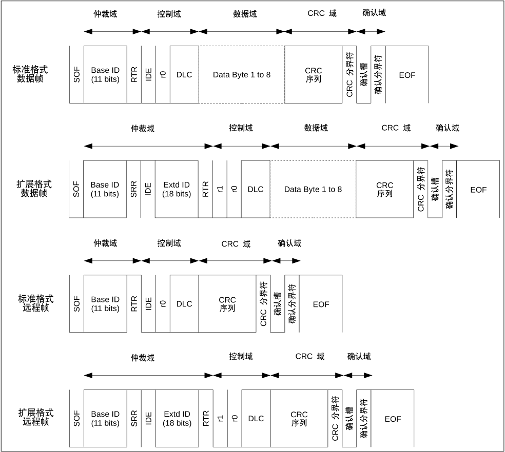
图:数据帧和远程帧中的位域
仲裁域 当两个或多个节点同时发送数据帧和远程帧时,将根据仲裁域的位信息来决定总线上获得优先仲裁的节点。在仲裁域作用时,如果一个节点在发送隐性位的同时检测到了一个显性位(逻辑值为 0),这表示有其他节点优先于了这个隐性位(逻辑值为 1)。那么,这个发送隐性位的节点已丢失总线仲裁,应立即转为接收器。仲裁域主要由帧标识符组成。
根据显性位代表的逻辑值为 0,隐性位代表的逻辑值为 1,有以下规律:
ID 值最小的帧将总是获得仲裁。
如果 ID 和格式相同,由于数据帧的 RTR 位为显性位,数据帧将优先于远程帧。
如果 ID 的前 11 位相同,由于扩展帧的 SRR 位是隐性,因而标准格式帧将总优先于扩展格式帧。
控制域 控制域主要由数据长度代码 (DLC) 组成,DLC 表示一个数据帧中的负载的数据字节数量,或一个远程帧请求的数据字节数量。DLC 优先发送最高有效位。R0、R1为保留位,默认显性用于以后扩展使用。
数据域 数据域中包含一个数据帧真实负载的数据字节,可以填入1~8个字节的数据。远程帧中不包含数据域。
CRC部分(循环冗余校验)
CRC 域主要由 CRC 序列组成。CRC 序列是一个 15-bit 的循环冗余校验编码,根据数据帧或远程帧中的未填充内容(从 SOF 到数据域末尾的所有内容)中计算而来。最后有1位隐性位定界符位。CRC 字段用于校验信息是否正确。
确认域(ACK) 确认 (ACK) 域由确认槽和确认分界符组成,主要功能为:接收器向发送器报告已正确接收到有效报文。ACK中一共两位,靠近CRC界定符的一位是 应答间隙(ACK SLOT),另一位是应答界定符(ACK DELIMITER)。
表 :标准格式(SFF) 和 扩展格式(EFF) 中的数据帧和远程帧
数据 帧/远程帧 |
描述 |
|---|---|
SOF |
帧起始 (SOF) 是一个用于同步总线上节点的单个显性位。 |
Base ID |
基标识符 (ID.28 ~ ID.18) 是 SFF 的 11-bit 标识符,或者是 EFF 中 29-bit 标识符的前 11-bit,ID越小仲裁中优先级越高。 |
RTR |
远程发送请求位 (RTR) 显示当前报文是 数据帧(显性)还是远程帧(隐性)。这意味着,当某个数据帧 和一个远程帧有相同标识符时,数据帧始终优先于远程帧仲裁。 |
SRR |
在 EFF 中发送替代远程请求位 (SRR),以替代 SFF 中相同位置的 RTR 位。 |
IDE |
标识符扩展位 (IED) 显示当前报文是 SFF(显性)还是 EFF(隐性)。这意味着,当某 SFF 帧和 EFF 帧有相同基标识符时,SFF 帧将始终优先于 EFF 帧仲裁。 |
Extd ID |
扩展标识符 (ID.17 ~ ID.0) 是 EFF 中 29-bit 标识符的剩余 18-bit。 |
r1 |
r1(保留位 1)始终是显性位用于以后扩展。 |
r0 |
r0(保留位 0)始终是显性位用于以后扩展。 |
DLC |
数据长度代码 (DLC) 为 4-bits,且应包含 0 ~ 8 中任一数值。数据帧使用 DLC表示自身包含的数据字节数量。远程帧使用 DLC 表示从其他节点请求的数据字节数量。 |
数据字节 |
表示数据帧的数据负载量。该字节数量应与 DLC 的值 匹配。首先发送数据字节0,各数据字节优先发送最高有效位。 |
CRC 序列 |
CRC 序列是一个 15-bit 的循环冗余校验编码。 |
CRC 分界符 |
CRC 分界符是遵循 CRC 序列的单一隐性位。 |
确认槽 |
确认槽用于接收器节点,表示是否已成功接收数据 帧或远程帧。发送器节点将在确认槽中发送一个隐性位,如果接 收到的帧没有错误,则接收器节点应用一个显性位替代确认槽。 |
确 认分界符 |
确认分界符是一个单一的隐性位。 |
EOF |
帧结束 (EOF) 标志着数据帧或远程帧的结束,由七个隐性位组成。 |
6.13.3.2.2 错误帧和过载帧
错误帧 当某节点检测到总线错误时,将发送一个错误帧。错误帧由一个特殊的错误标志构成,该标志由某相同值的六个连续位组成,因而违反了位填充的规则。所以,当某节点检测到总线错误并发送错误帧时,其余节点也将相应地检测到一个填充错误并各自发送错误帧。也就是说,当发生总线错误时,通过上述过程可将该报文传递至总线上的所有节点。 当某节点检测到总线错误时,该节点将于下一个位发送错误帧。特例:如果总线错误类型为 CRC 错误,那么错误帧将从确认分界符的下一个位开始。
下图所示为一个错误帧所包含的不同域:

图 : 错误帧中的位域 表: 错误帧
错误帧 |
描述 |
|---|---|
错误标志 |
错误标志包括两种形式: 主动错误标志和被动错误标志,主动错误标志由 6 个显性位组成,被动错误标志由 6 个隐性位组成(被其他节点的显性位优先仲裁时除外)。主动 错误节点发送主动错误标志,被动错误节点发送被动错误标志。 |
错误 标志叠加 |
错误标志叠加域的主要目的是允许总 线上的其他节点发送各自的主动错误标志。叠加域的范围可以是 0 ~ 6 位,在 检测到第一个隐性位时结束(如检测到分界符上的第一个位)。 |
错 误分界符 |
分界符域标志着错误/过载帧结束,由 8 个隐性位构成。 |
过载帧 过载帧与包含主动错误标志的错误帧有着相同的位域。二者主要区别在于触发发送过载帧的条件。下图所示为过载帧中包含的位域:

图: 过载帧中的位域
表 : 过载帧
过载帧 |
描述 |
|---|---|
过载标志 |
由 6 个显性位构成。与主动错误标志相同。过载标志叠加 允许其他节点发送过载标志的叠加,与错误标志叠加相似。 |
过载分界符 |
由 8 个隐性位构成。与错误分界符相同。 |
下列情况将触发发送过载帧:
接收器内部要求延迟发送下一个数据帧或远程帧。
在间歇域后的首个和第二个位上检测到显性位。
如果在错误分界符的第八个(最后一个)位上检测到显性位。请注意,在这种情况下 TEC 和 REC 的值将不会增加。
由于上述情况发送过载帧时,须满足以下规定:
第 1 条情况下发送的过载帧只能从间歇域后的第一个位开始。
第 2、3 条情况下发送的过载帧须从检测到显性位的后一个位开始。
要延迟发送下一个数据帧或远程帧,最多可生成两个过载帧。
6.13.3.2.3 帧间距
帧间距充当各帧之间的分隔符。数据帧和远程帧必须与前一帧用一个帧间距分隔开,不论前面的帧是何类型(数据帧、远程帧、错误帧、过载帧)。但是,错误帧和过载帧则无需与前一个帧分隔开。 下图所示为帧间距中包含的域:
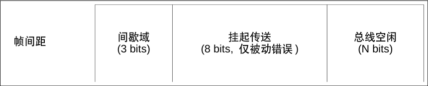
图: 帧间距中的域 表: 帧间距
帧间距 |
描述 |
|---|---|
间歇域 |
间歇域由 3 个隐性位构成。 |
挂起传送 |
被动错误节点发送报文后,节点中须包含一个挂起传送域,由 8 个隐性位构成。主动错误节点中不含这个域。 |
总线空闲 |
总线空闲域长度任意。发送 SOF 时,总线空闲结束。若节点中有挂起传送,则 SOF应在间歇域后的第一位发送。 |
6.13.3.3 CAN Bus 错误
6.13.3.3.1 错误类型
CAN Bus 中的总线错误包括以下类型:
位错误 当节点发送一个位值(显性位或隐性位)但回读到相反的位时(如,发送显性位时检测到了隐性位),就会发生位错误。但是,如果发送的位是隐性位,且位于仲裁域或确认槽或被动错误标志中,那么此时检测到显性位的话也不会认定为位错误。
填充错误 当检测到相同值的 6 个连续位时(违反位填充的编码规则),发生填充错误。
CRC 错误 数据帧和远程帧的接收器将根据接收到的位计算 CRC 值。当接收器计算的值与接收到的数据帧和远程帧中的 CRC 序列不匹配时,会发生 CRC 错误。
格式错误 当某个报文中的固定格式位中包含非法位时,可检测到格式错误。比如,r1 和 r0 域必须固定为显性却检测到隐性。
确认错误 当发送器无法在确认槽中检测到显性位时,将发生确认错误。
6.13.3.3.2 错误状态
CAN Bus 通过每个节点维护两个错误计数来实现故障界定,计数数值决定错误状态。这两个错误计数分别为:发送错误计数 (TEC) 和接收错误计数 (REC)。CAN Bus 包含以下错误状态:
主动错误 Error Active 主动错误节点可参与到总线交互中,且在检测到错误时可以发送主动错误标志。
被动错误 Error Passive 被动错误节点可参与到总线交互中,但在检测到错误时只能发送一次被动错误标志。被动错误节点发送数据帧或远程帧后,须在后续的帧间距中设置挂起传送域。
离线 Bus-Off 禁止离线节点以任意方式干扰总线(如,不允许其进行数据传输)。
6.13.3.3.3 错误计数
TEC 和 REC 根据以下规则递增/递减。请注意,一条报文传输中可应用多个规则。
当接收器检测到错误时,REC 数值将增加 1。当检测到的错误为发送主动错误标志或过载标志期间的位错误除外。
发送错误标志后,当接收器第一个检测到的位是显性位时,REC 数值将增加 8。
当发送器发送错误标志时,TEC 数值增加 8。但是,以下情况不适用于该规则:
发送器为被动错误状态,因为在应答槽未检测到显性位而产生应答错误,且在发送被动错误标志时检测到显性位时,则 TEC 数值不应增加。
发送器在仲裁期间因填充错误而发送错误标志,且填充位本该是隐性位但是检测到显性位,则 TEC 数值不应增加。
若发送器在发送主动错误标志和过载标志时检测到位错误,则 TEC 数值增加 8。
若接收器在发送主动错误标志和过载标志时检测到位错误,则 REC 数值增加 8。
任意节点在发送主动/被动错误标志或过载标志后,节点仅能承载最多 7 个连续显性位。在(发送主动错误标志或过载标志时)检测到第 14 个连续显性位,或在被动错误标志后检测到第 8 个连续显性位后,发送器将使其 TEC 数值增加 8,而接收器将使其 REC 数值增加 8。每增加 8 个连续显性位的同时,(发送器的)TEC 和(接收器的)REC 数值也将增加 8。
每当发送器成功发送报文后(接收到 ACK,且直到 EOF 完成未发生错误),TEC 数值将减小 1,除非 TEC的数值已经为 0。
当接收器成功接收报文后(确认槽前未检测到错误,且成功发送 ACK),则 REC 数值将相应减小。
若 REC 数值位于 1 ~ 127 之间,则其值减小 1。
若 REC 数值大于 127,则其值减小到 127。
若 REC 数值为 0,则仍保持为 0。
当一个节点的 TEC 和/或 REC 数值大于等于 128 时,该节点变为被动错误节点。导致节点发生上述状态切换的错误,该节点仍发送主动错误标志。请注意,一旦 REC 数值到达 128,后续任何增加该值的动作都是无效的,直到 REC 数值返回到 128 以下。
当某节点的 TEC 数值大于等于 256 时,该节点将变为离线节点。
当某被动错误节点的 TEC 和 REC 数值都小于等于 127,则该节点将变为主动错误节点。
当离线节点在总线上检测到 128 次 11 个连续隐性位后,该节点可变为主动错误节点(TEC 和 REC 数值都重设为 0)。
6.13.3.4 CAN Bus 位时序
6.13.3.4.1 名义位
CAN Bus 协议允许 CAN Bus 以特定的位速率运行。但是,总线内的所有节点必须以统一位速率运行。
名义位速率为每秒发送比特数量。
名义位时间为 1/名义位速率。
每个名义位时间中含多个段,每段由多个时间定额 (Time Quanta) 组成。时间定额为最小时间单位,作为一种预分频时钟信号应用于各个节点中。下图所示为一个名义位时间内所包含的段。
CAN Bus 控制器将在一个时间定额的时间步长中进行操作,每个时间定额中都会分析 CAN Bus 的总线状态。如果两个连续的时间定额中总线状态不同(隐性-显性,或反之),意味着有边沿产生。PBS1 和 PBS2 的交点将被视为采样点,且采样的总线数值即为这个位的数值。
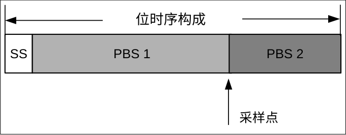
图: 位时序构成
表: 名义位时序中包含的段
段 |
描述 |
|---|---|
同步段 (SS) |
SS(同步段)的长度为 1 个时间 定额。若所有节点都同步正常,则位边沿应位于该段内。 |
缓冲时期段 1 (PBS1) |
PBS1 的长度可为 1 ~ 16 个时间定额,用于补偿网络中的物理延迟时间。可增加 PBS1的长度,从而更好地实现同步。 |
缓冲时期段 2 (PBS2) |
PBS2 的长度可为 1 ~ 8 个时间定额,用于补偿节点中的信息处理时间。可缩短 PBS2的长度,从而更好地实现同步。 |
6.13.3.4.2 硬同步与再同步
由于时钟偏移和抖动,同一总线上节点的位时序可能会脱离相位段。因而,位边沿可能会偏移到同步段的前后。 针对上述位边沿偏移的问题 CAN Bus 提供多种同步方式。设位边沿偏移的 TQ(时间定额)数量为相位错误“e”,该值与 SS 相关。
主动相位错误 (e > 0):位边沿位于同步段之后采样点之前(即,边沿向后偏移)。
被动相位错误 (e < 0):位边沿位于前个位的采样点之后同步段之前(即,边沿向前偏移)。
为解决相位错误,可进行两种同步方式,即硬同步与再同步。硬同步与再同步遵守以下规则:
单个位时序中仅可发生一次同步。
同步仅可发生在隐性位到显性位的边沿上。
硬同步 总线空闲期间,硬同步发生在隐性位到显性位的变化边沿上(如 SOF 位上)。此时,所有节点都将重启其内部 位时序,从而使该变化边沿位于重启位时序的同步段内。
再同步 非总线空闲期间,再同步发生在隐性位到显性位的变化边沿上。如果边沿上有主动相位错误 (e > 0),则 PBS1 长度将增加。如果边沿上有被动相位错误 (e < 0),则 PBS2 长度将减小。
PBS1/PBS2 具体增加和减小的时间定额取决于相位错误的绝对值,同时也受可配置的同步跳宽 (SJW) 数值限制。
当相位错误的绝对值小于等于 SJW 数值时,PBS1/PBS2 将增加/减小 e 个时间定额。该过程与硬同步具有相同效果。
当相位错误的绝对值大于 SJW 数值时,PBS1/PBS2 将增加/减小与 SJW 相同数值的时间定额。这意味着,在完全解决相位错误之前,可能需要多个同步位。
6.13.4 驱动程序配置
本节介绍如何配置 CAN Bus 驱动程序。
6.13.4.1 操作模式
CAN Bus 驱动程序支持以下操作模式:
正常模式 Normal Mode:正常操作模式允许 CAN Bus 控制器参与总线活动,例如发送和接收消息/错误帧。传输消息时需要来自另一个节点的确认。
无应答模式 No Ack Mode: No Acknowledgment 模式类似于正常模式,但是消息传输不需要确认即可被视为成功。此模式在自测 CAN Bus 控制器(传输环回)时很有用。
只听模式 Listen Only Mode:此模式将防止 CAN Bus 控制器影响总线。因此,消息/确认/错误帧的传输将被禁用。然而,CAN Bus 控制器仍然能够接收消息,但不会确认消息。该模式适用于总线监控应用。
6.13.4.2 警报
CAN 驱动程序包含一个警报功能,用于通知应用层某些 CAN 控制器或 CAN 总线事件。安装 CAN 驱动程序时有选择地启用警报,但可以在运行时通过调用重新配置 can_reconfigure_alerts()。然后,应用程序可以通过调用 等待任何启用的警报发生 can_read_alerts()。CAN 驱动程序支持以下警报:
警报标志 |
描述 |
|---|---|
|
不再有消息排队等待传输 |
|
上一次传输成功 |
|
已接收到一帧并将其添加到 RX 队列中 |
|
两个错误计数器都低于错误警告限制 |
|
CAN Bus 控制器已激活错误 |
`` CAN_ALERT_RECOVERY_IN_PROGRESS`` |
CAN Bus 控制器正在进行总线恢复 |
|
CAN Bus 控制器已成功完成总线恢复 |
|
上一次传输丢失仲裁 |
|
错误计数器之一已超过错误警告限制 |
|
总线上发生 (位、填充、CRC、表格、ACK)错误 |
|
上一次传输失败 |
|
RX 队列已满导致接收到的帧丢失 |
|
CAN Bus 控制器已成为被动错误 |
|
发生总线关闭情况。CAN Bus 控制器不能再影响总线 |
6.13.4.3 位时序
CAN Bus 驱动程序的操作比特率是使用该 can_timing_config_t结构配置的。每个位的周期由多个时间段组成,时间段的周期由 CAN Bus 控制器源时钟的预分频版本决定。单个位按以下顺序包含以下段:
同步段由单个时间段组成
时序段 1由采样点之前的 1 到 16 个时间量子组成
时序段 2由采样点之后的 1 到 8 个时间量子组成
波特率预分频器用于对 CAN Bus 控制器的源时钟(80 MHz APB
时钟)进行分频来确定每个时间段的周期。在 ESP32
上,brp可以是从 2 到 128 的任何偶数。
如果 ESP32 是版本 2 或更高版本的芯片,它brp还将支持从 132 到
256 的任何 4
的倍数,并且可以通过将CONFIG_ESP32_REV_MIN设置为版本
2 或更高版本来启用。
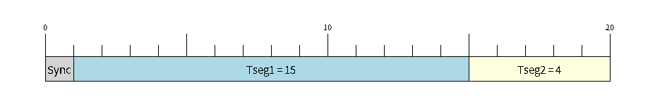
给定 BRP = 8 的 500kbit/s 的位时序配置
位的采样点位于时序段 1 和时序段 2 的交叉点。启用三重采样将导致每个位采样 3 个时间量子而不是 1 个(额外的样本位于时序段 1 的尾部)。
同步跳转宽度用于确定单个位时间可以为同步目的延长/缩短的最大时间量。sjw范围可以从
1 到 4。
注解
brp、tseg_1、tseg_2和的多种组合sjw可以实现相同的比特率。用户应通过考虑传播延迟、节点信息处理时间和相位误差等因素,将这些值调整到其总线的物理特性。
位时序宏初始化器也可用于常用的位速率。以下宏初始化程序由 CAN Bus 驱动程序提供。
CAN_TIMING_CONFIG_1MBITS()CAN_TIMING_CONFIG_800KBITS()CAN_TIMING_CONFIG_500KBITS()CAN_TIMING_CONFIG_250KBITS()CAN_TIMING_CONFIG_125KBITS()CAN_TIMING_CONFIG_100KBITS()CAN_TIMING_CONFIG_50KBITS()CAN_TIMING_CONFIG_25KBITS()
6.13.4.4 验收过滤器
CAN Bus 控制器包含一个硬件验收过滤器,可用于过滤特定ID的消息。过滤出消息的节点不会接收到该消息,但仍会对其进行确认。验收过滤器可以过滤掉通过总线发送的与节点无关的消息来提高节点的效率。验收过滤器使用两个 32 位配置值验收代码和验收掩码来配置验收过滤器(can_filter_config_t结构体变量)。
验收代码: 指定消息的 ID、RTR 和数据字节必须匹配的位序列,以便 CAN Bus 控制器接收消息。
验收屏蔽: 是一个位序列,指定可以忽略验收代码的哪些位。这允许单个验收代码验收不同 ID 的消息。
验收滤波器可在单或双滤波器模式下使用。单过滤器模式将使用验收代码和掩码来定义单个过滤器。这允许过滤标准帧的前两个数据字节,或整个扩展帧的 29 位 ID。下图说明了在单过滤模式下如何解释 32 位验收代码和掩码(注意:黄色和蓝色字段分别代表标准和扩展帧格式)。
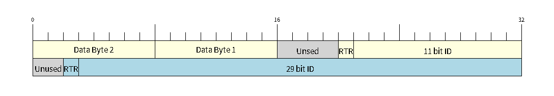
单滤波器模式的位布局(右侧MSBit)
双过滤器模式将使用验收代码和掩码来定义两个单独的过滤器,从而增加验收 ID 的灵活性,但不允许过滤扩展 ID 的所有 29 位。下图说明了在双滤波器模式下如何解释 32 位验收代码和掩码(注意:黄色和蓝色字段分别代表标准和扩展帧格式)。
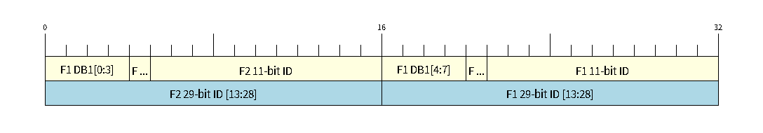
双滤波器模式的位布局(右侧MSBit)
6.13.5 API参考
init() - 安装 CAN Bus 驱动程序
语法
bool init(const can_general_config_t *g_config, const can_timing_config_t *t_config, const can_filter_config_t *f_config);
参数
参数 |
说明 |
值范围 |
|---|---|---|
g_config |
CAN driver 常规配置结构体 |
|
t_config |
CAN driver 定时配置结构体 |
|
f_config |
CAN driver 过滤器配置结构体 |
返值
返回值 |
说明 |
值范围 |
|---|---|---|
bool |
true:成功安装CAN驱动程序false:安装CAN驱动程序失败 |
release() - 卸载 CAN Bus 驱动程序
语法
bool release();
参数
无
返值
返回值 |
说明 |
值范围 |
|---|---|---|
bool |
true:CAN 驱动卸载 成功false:驱动程序未处于停止/下车状态,或未安装 |
start() - 启动 CAN Bus 驱动程序
语法
bool start();
参数
无
返回
返回值 |
说明 |
值范围 |
|---|---|---|
bool |
true:CAN 驱动 开始运行false:驱动程序未处于停止状态,或未安装 |
stop() - 停止 CAN Bus 驱动程序
语法
bool stop();
参数
无
返值
返回值 |
说明 |
值范围 |
|---|---|---|
bool |
true:CAN 驱动 已经停止false:驱动程序未处于运行状态,或未安装 |
transmit() - 发送 CAN Bus 信息
从RX队列接收消息。消息结构的Flag字段将指示接收的消息类型。如果接收队列中没有消息,此功能将被阻止
语法
bool transmit(const can_message_t *message, TickType_t ticks_to_wait);
参数
参数 |
说明 |
值范围 |
|---|---|---|
message |
需要传输的消息 |
|
ticks_to_wait |
在TX队列上阻塞的FreeRTOS滴答数 |
返回
返回值 |
说明 |
值范围 |
|---|---|---|
bool |
true:传输成功排队/启动false:传输失败 |
这里我们默认设置为心跳频率为1000
receive() - 接收 CAN Bus 消息
语法
bool receive(can_message_t *message, TickType_t ticks_to_wait);
参数
参数 |
说明 |
值范围 |
|---|---|---|
message |
存放接收消息的结构体 |
|
ticks_to_wait |
在RX队列上阻塞的FreeRTOS滴答数 |
返回
返回值 |
说明 |
值范围 |
|---|---|---|
bool |
true:从RX队列成功接收消息false:从RX队列未成功接收到消息 |
readAlerts() - 阅读 CAN Bus 驱动程序警报
语法
bool readAlerts(uint32_t *alerts, TickType_t ticks_to_wait);
参数
参数 |
说明 |
值范围 |
|---|---|---|
alerts |
引发警报的位域(参见文档中的警报标志) |
|
ticks_to_wait |
用于阻塞警报的FreeRTOS滴答数 |
返回
返回值 |
说明 |
值范围 |
|---|---|---|
bool |
true:警报读取成功false:警报读取失败 |
reconfigureAlerts() - 重新配置启用警报
语法
bool reconfigureAlerts(uint32_t alerts_enabled, uint32_t *current_alerts);
参数
参数 |
说明 |
值范围 |
|---|---|---|
alerts_enabled |
要启用的警报的位域(参见文档中的警报标志) |
|
current_alerts |
当前发出警报的位域。如果不使用,设置为NULL |
返回
返回值 |
说明 |
值范围 |
|---|---|---|
bool |
true:警报重新配置false:CAN Bus 驱动没有安装 |
initiateRecovery() - 启动总线恢复进程
还记得 CAN Bus 的TEC计数大于或等于256时会改变节点状态为离线状态吗?
这个函数在你想要恢复离线节点时调用。
语法
bool initiateRecovery(void);
返回
返回值 |
说明 |
值范围 |
|---|---|---|
bool |
true:启动总线 恢复false:驱动程序未处于总线关闭状态或者未安装 |
getStatusInfo() - 获取CAN驱动程序的当前状态信息
语法
bool getStatusInfo(can_status_info_t *status_info);
参数
参数 |
说明 |
值范围 |
|---|---|---|
status_info |
状态信息 |
返回
返回值 |
说明 |
值范围 |
|---|---|---|
bool |
true:获取成功false:获取失败 |
clearTransmitQueue() - 清除传输队列
语法
bool clearTransmitQueue(void);
参数
无
返回
返回值 |
说明 |
值范围 |
|---|---|---|
bool |
true:传输队列已经清除false:CAN Bus 驱动程序没有安装或TX队列被禁用 |
clearReceiveQueue() - 清除接收队列
语法
bool clearReceiveQueue(void);
参数
无
返值
返回值 |
说明 |
值范围 |
|---|---|---|
bool |
true:接收队列已经清除false:CAN驱动程序没有安装 |
例程:CAN Bus 接收
本例程展示了 Edge101WE 主板使用 CAN Bus 来接收帧数据,并且判断帧数据是什么类型。用户还可以通过用户按键来关闭 CAN Bus 功能。
接线图:
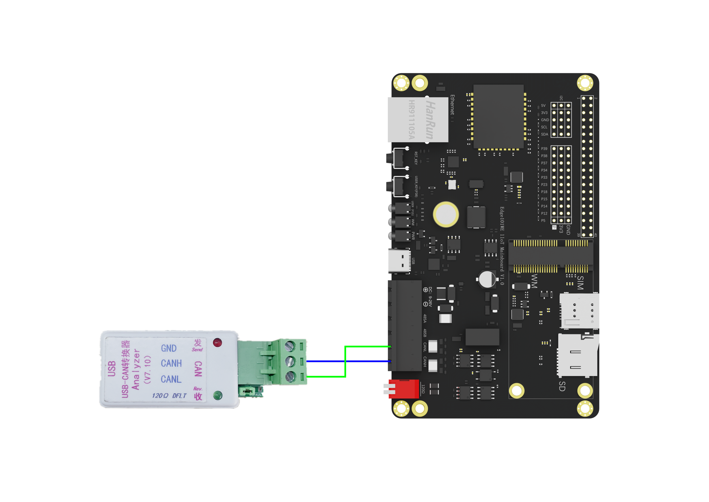
#include "DFRobot_ESP32CAN.h"

DFRobot_ESP32CAN ESP32Can;
uint8_t userKey = 38;
can_message_t message;

//外部中断函数,关闭CAN
void interEvent(void){
  ESP32Can.clearReceiveQueue(); //清空RX队列
  ESP32Can.stop();              //停止CAN驱动阻止进一步收发
  ESP32Can.release();           //卸载CAN驱动
  detachInterrupt(userKey);     //卸载设置的中断引脚
}

void setup() {

  pinMode(userKey, INPUT_PULLUP);
  attachInterrupt(userKey,interEvent,CHANGE);

  Serial.begin(115200);

  /*请到 DFRobot_ESP32CAN.h 中找到 can_general_config_t 这个结构体内容和 CAN_GENERAL_CONFIG_DEFAULT(op_mode) 进一步了解和修改部分内容。

  函数功能:更改CAN的模式

  模式
  CAN_MODE_NORMAL  正常 发送/接收/确认 模式
  CAN_MODE_NO_ACK  发送无确认传输模式,用于自检
  CAN_MODE_LISTEN_ONLY  不影响总线模式(不会发送和确认但可以接收消息)
   */
  can_general_config_t g_config = CAN_GENERAL_CONFIG(CAN_MODE_NORMAL);  //将更改好的内容给 g_config 一般配置,用于初始化

  /*请到 DFRobot_ESP32CAN.h 中找到 can_timing_config_t 这个结构体内容和 CAN_TIMING_CONFIG_500KBITS()  进一步了解和修改部分内容。

  函数功能:更改波特率

  可选波特率:
  CAN_TIMING_CONFIG_25KBITS()
  CAN_TIMING_CONFIG_50KBITS()
  CAN_TIMING_CONFIG_100KBITS()
  CAN_TIMING_CONFIG_125KBITS()
  CAN_TIMING_CONFIG_250KBITS()
  CAN_TIMING_CONFIG_500KBITS()
  CAN_TIMING_CONFIG_800KBITS()
  CAN_TIMING_CONFIG_1MBITS()
  */
  can_timing_config_t t_config = CAN_TIMING_CONFIG_500KBITS();  //将设置好内容给 t_config 定时配置,用于初始化

  /*  请到 DFRobot_ESP32CAN.h 中找到 can_filter_config_t 这个结构体内容和 CAN_FILTER_CONFIG_ACCEPT_ALL()  进一步了解和修改部分内容。

  CAN_FILTER_CONFIG_ACCEPT_ALL()  {.acceptance_code = 0, .acceptance_mask = 0xFFFFFFFF, .single_filter = true}

  函数功能:配置过滤器,默认屏蔽位全部为1,这表示标识符必须完全一样才会接收。
   */
  can_filter_config_t f_config = CAN_FILTER_CONFIG_ACCEPT_ALL();

  //将配置好的参数放入初始化函数
  while(!ESP32Can.init(&g_config,&t_config,&f_config)){
    Serial.println("CAN init err!!!");
    delay(1000);
  }

  //安装CAN驱动,重置RX、TX队列以及RX接收消息的计数
  while(!ESP32Can.start()){
    Serial.println("CAN start err!!!");
    delay(1000);
  }
}

void loop() {
  // 接收信息函数,message 为总线上的报文,pdMS_TO_TICKS() 设置阻塞,就是等待自己想要的数据的规定时间,单位1ms
  if(ESP32Can.receive(&message,pdMS_TO_TICKS(1000))){
    // 所要接收id,可通过添加||来允许接收多个ID
    if(message.identifier == 0x0006){
    /*可到 DFRobot_ESP32CAN.h 中找到 Message flags 查看
        flags:
        CAN_MSG_FLAG_NONE   标准格式
        CAN_MSG_FLAG_EXTD   扩展格式
        CAN_MSG_FLAG_RTR    遥控帧(远程帧)
        CAN_MSG_FLAG_SS     报错不重发
        CAN_MSG_FLAG_SELF   自接收请求
    */
      if (message.flags == CAN_MSG_FLAG_NONE) {
        Serial.println("Message is in Standard Format");
      } else if(message.flags == CAN_MSG_FLAG_EXTD){
        Serial.println("Message is in Extended Format");
      } else if(message.flags == CAN_MSG_FLAG_RTR){
        Serial.println("Message is a Remote Transmit Request");
      } else if(message.flags == CAN_MSG_FLAG_SS){
        Serial.println("Transmit as a Single Shot Transmission");
      } else if(message.flags == CAN_MSG_FLAG_SELF){
        Serial.println("Transmit as a Self Reception Request");
      } else if(message.flags == CAN_MSG_FLAG_DLC_NON_COMP){
        Serial.println("Message's Data length code is larger than 8. This will break compliance with CAN2.0B");
      }
      //message.data_length_code 在 g_config 中已默认为 5字符作为传输字符数
      for (int i = 0; i < message.data_length_code; i++) {
        Serial.printf("Data byte %d = %d\n", i, message.data[i]);
      }
    }else{
      printf("err id:%d\n",message.identifier);
    }
  } else{
    Serial.println("Failed to queue message for receive");
  }
  delay(10);
}
将以上代码下载到主板。
通过USB CAN分析器发送数据给主板。
主板A的CAN总线接收到数据并通过USB串口输出
Message is in Standard Format
Data byte 0 = 17
Data byte 1 = 34
Data byte 2 = 51
Data byte 3 = 68
Data byte 4 = 85
Data byte 5 = 102
Data byte 6 = 119
Data byte 7 = 136
例程:CAN Bus 发送
本例程展示了 Edge101WE 主板使用 CAN Bus 来发送标准帧数据,并且可通过用户按键关闭 CAN Bus 功能。
接线图:
/*!
 * @file can_send.ino
 * @brief 本demo展示了FireBeetle MESH - Industrial IoT Mainboard 使用CAN来发送标准帧数据,并且可通过用户按键关闭CAN功能
 * @copyright Copyright (c) 2010 DFRobot Co.Ltd (http://www.dfrobot.com)
 * @licence The MIT License (MIT)
 * @author [yangfeng]<feng.yang@dfrobot.com>
 * @version V1.0
 * @date 2021-04-08
 * @get from https://www.dfrobot.com
 */
#include "DFRobot_ESP32CAN.h"

DFRobot_ESP32CAN ESP32Can;
uint8_t userKey = 38;
can_message_t tx_message;

void interEvent(void){
  ESP32Can.stop();
  ESP32Can.release();
  detachInterrupt(userKey);
}

void setup() {
  pinMode(userKey, INPUT_PULLUP);
  attachInterrupt(digitalPinToInterrupt(userKey),interEvent,CHANGE);  //Enable external interrupts

  Serial.begin(9600);

  /**  这里对can_general_config_t这个结构体内容进行注释说明,对于 MESH 开发板我们默认CAN的收发IO口为GPIO_35、GPIO_32
   *
   * typedef struct {
   *     can_mode_t mode;                < Mode of CAN controller
   *     gpio_num_t tx_io;               < Transmit GPIO number
   *     gpio_num_t rx_io;               < Receive GPIO number
   *     gpio_num_t clkout_io;           < CLKOUT GPIO number (optional, set to -1 if unused)
   *     gpio_num_t bus_off_io;          < Bus off indicator GPIO number (optional, set to -1 if unused)
   *     uint32_t tx_queue_len;          < Number of messages TX queue can hold (set to 0 to disable TX Queue)
   *     uint32_t rx_queue_len;          < Number of messages RX queue can hold
   *     uint32_t alerts_enabled;        < Bit field of alerts to enable
   *     uint32_t clkout_divider;        < CLKOUT divider. Can be 1 or any even number from 2 to 14 (optional, set to 0 if unused)
   *     int intr_flags;                 < Interrupt flags to set the priority of the driver's ISR. Note that to use the ESP_INTR_FLAG_IRAM, the CONFIG_CAN_ISR_IN_IRAM option should be enabled first.
   * } can_general_config_t;
   *
   * mode:
   *     CAN_MODE_NORMAL,                < Normal operating mode where CAN controller can send/receive/acknowledge messages
   *     CAN_MODE_NO_ACK,                < Transmission does not require acknowledgment. Use this mode for self testing
   *     CAN_MODE_LISTEN_ONLY,           < The CAN controller will not influence the bus (No transmissions or acknowledgments) but can receive messages
   *
   * CAN_GENERAL_CONFIG_DEFAULT(op_mode) {.mode = op_mode, .tx_io = GPIO_NUM_32, .rx_io = GPIO_NUM_35,   \
   *                                      .clkout_io = CAN_IO_UNUSED, .bus_off_io = CAN_IO_UNUSED,       \
   *                                      .tx_queue_len = 5, .rx_queue_len = 5,                          \
   *                                      .alerts_enabled = CAN_ALERT_NONE,  .clkout_divider = 0,        \
   *                                      .intr_flags = ESP_INTR_FLAG_LEVEL1}
   */
  can_general_config_t g_config = CAN_GENERAL_CONFIG(CAN_MODE_NORMAL);

  /** 这里对can_timing_config_t这个结构体内容进行注释说明,用户可以直接选用使用初始化宏来配置CAN的通信速率
   * typedef struct {
   *  uint32_t brp;                   < Baudrate prescaler (i.e., APB clock divider) can be any even number from 2 to 128.
   *                                    For ESP32 Rev 2 or later, multiples of 4 from 132 to 256 are also supported
   *  uint8_t tseg_1;                 < Timing segment 1 (Number of time quanta, between 1 to 16)
   *  uint8_t tseg_2;                 < Timing segment 2 (Number of time quanta, 1 to 8)
   *  uint8_t sjw;                    < Synchronization Jump Width (Max time quanta jump for synchronize from 1 to 4)
   *  bool triple_sampling;           < Enables triple sampling when the CAN controller samples a bit
   * } can_timing_config_t;
   *
   * CAN_TIMING_CONFIG_25KBITS()     {.brp = 128, .tseg_1 = 16, .tseg_2 = 8, .sjw = 3, .triple_sampling = false}
   * CAN_TIMING_CONFIG_50KBITS()     {.brp = 80, .tseg_1 = 15, .tseg_2 = 4, .sjw = 3, .triple_sampling = false}
   * CAN_TIMING_CONFIG_100KBITS()    {.brp = 40, .tseg_1 = 15, .tseg_2 = 4, .sjw = 3, .triple_sampling = false}
   * CAN_TIMING_CONFIG_125KBITS()    {.brp = 32, .tseg_1 = 15, .tseg_2 = 4, .sjw = 3, .triple_sampling = false}
   * CAN_TIMING_CONFIG_250KBITS()    {.brp = 16, .tseg_1 = 15, .tseg_2 = 4, .sjw = 3, .triple_sampling = false}
   * CAN_TIMING_CONFIG_500KBITS()    {.brp = 8, .tseg_1 = 15, .tseg_2 = 4, .sjw = 3, .triple_sampling = false}
   * CAN_TIMING_CONFIG_800KBITS()    {.brp = 4, .tseg_1 = 16, .tseg_2 = 8, .sjw = 3, .triple_sampling = false}
   * CAN_TIMING_CONFIG_1MBITS()      {.brp = 4, .tseg_1 = 15, .tseg_2 = 4, .sjw = 3, .triple_sampling = false}
   */
  can_timing_config_t t_config = CAN_TIMING_CONFIG_500KBITS();

  /**  这里对can_filter_config_t这个结构体内容进行注释说明,用户可以直接选用使用初始化宏来配置接收过滤器
   *
   * typedef struct {
   *  uint32_t acceptance_code;       < 32-bit acceptance code
   *  uint32_t acceptance_mask;       < 32-bit acceptance mask
   *  bool single_filter;             < Use Single Filter Mode
   * } can_filter_config_t;
   *
   * CAN_FILTER_CONFIG_ACCEPT_ALL()  {.acceptance_code = 0, .acceptance_mask = 0xFFFFFFFF, .single_filter = true}
   *
   */
  can_filter_config_t f_config = CAN_FILTER_CONFIG_ACCEPT_ALL();

  while(!ESP32Can.init(&g_config,&t_config,&f_config)){
    Serial.println("CAN init err!!!");
    delay(1000);
  }

  while(!ESP32Can.start()){
    Serial.println("CAN start err!!!");
    delay(1000);
  }
  ESP32Can.clearTransmitQueue();
  tx_message.identifier = 0x0006;
  tx_message.data_length_code = 4;
  /**flags:
   *   CAN_MSG_FLAG_NONE                       < No message flags (Standard Frame Format)
   *   CAN_MSG_FLAG_EXTD                       < Extended Frame Format (29bit ID)
   *   CAN_MSG_FLAG_RTR                        < Message is a Remote Transmit Request
   *   CAN_MSG_FLAG_SS                         < Transmit as a Single Shot Transmission
   *   CAN_MSG_FLAG_SELF                       < Transmit as a Self Reception Request
   */
  tx_message.flags = CAN_MSG_FLAG_NONE;
  tx_message.data[0] = 0;
  tx_message.data[1] = 1;
  tx_message.data[2] = 2;
  tx_message.data[3] = 3;
}

void loop() {
  if(ESP32Can.transmit(&tx_message,pdMS_TO_TICKS(1000))){
    Serial.println("Message queued for transmission");
  } else{
    Serial.println("Failed to queue message for transmission");
  }

  delay(1000);
}
将代码下载到另外一块主板。主板每一秒发送一个数据帧。将主板的 CAN Bus 连接到USB CAN分析器。
USB CAN分析器接收到主板发送的数据
例程:获取在 CAN Bus 传输中的警报
例程将 CAN Bus 的警报类型通过主板USB串口打印出来。
/*!
 * @file can_alert.ino
 * @brief 本demo展示了如何获取在CAN传输中的警报
 * @copyright Copyright (c) 2010 DFRobot Co.Ltd (http://www.dfrobot.com)
 * @licence The MIT License (MIT)
 * @author [yangfeng]<feng.yang@dfrobot.com>
 * @version V1.0
 * @date 2021-04-08
 * @get from https://www.dfrobot.com
 */
#include "DFRobot_ESP32CAN.h"
DFRobot_ESP32CAN ESP32Can;
can_message_t tx_message;

void setup() {

  Serial.begin(9600);

  /**  这里对can_general_config_t这个结构体内容进行注释说明,对于 MESH 开发板我们默认CAN的收发IO口为GPIO_35、GPIO_32
   *
   * typedef struct {
   *     can_mode_t mode;                < Mode of CAN controller
   *     gpio_num_t tx_io;               < Transmit GPIO number
   *     gpio_num_t rx_io;               < Receive GPIO number
   *     gpio_num_t clkout_io;           < CLKOUT GPIO number (optional, set to -1 if unused)
   *     gpio_num_t bus_off_io;          < Bus off indicator GPIO number (optional, set to -1 if unused)
   *     uint32_t tx_queue_len;          < Number of messages TX queue can hold (set to 0 to disable TX Queue)
   *     uint32_t rx_queue_len;          < Number of messages RX queue can hold
   *     uint32_t alerts_enabled;        < Bit field of alerts to enable
   *     uint32_t clkout_divider;        < CLKOUT divider. Can be 1 or any even number from 2 to 14 (optional, set to 0 if unused)
   *     int intr_flags;                 < Interrupt flags to set the priority of the driver's ISR. Note that to use the ESP_INTR_FLAG_IRAM, the CONFIG_CAN_ISR_IN_IRAM option should be enabled first.
   * } can_general_config_t;
   *
   * mode:
   *     CAN_MODE_NORMAL,                < Normal operating mode where CAN controller can send/receive/acknowledge messages
   *     CAN_MODE_NO_ACK,                < Transmission does not require acknowledgment. Use this mode for self testing
   *     CAN_MODE_LISTEN_ONLY,           < The CAN controller will not influence the bus (No transmissions or acknowledgments) but can receive messages
   *
   * CAN_GENERAL_CONFIG_DEFAULT(op_mode) {.mode = op_mode, .tx_io = GPIO_NUM_32, .rx_io = GPIO_NUM_35,   \
   *                                      .clkout_io = CAN_IO_UNUSED, .bus_off_io = CAN_IO_UNUSED,       \
   *                                      .tx_queue_len = 5, .rx_queue_len = 5,                          \
   *                                      .alerts_enabled = CAN_ALERT_NONE,  .clkout_divider = 0,        \
   *                                      .intr_flags = ESP_INTR_FLAG_LEVEL1}
   */
  can_general_config_t g_config = CAN_GENERAL_CONFIG(CAN_MODE_NORMAL);

  /** 这里对can_timing_config_t这个结构体内容进行注释说明,用户可以直接选用使用初始化宏来配置CAN的通信速率
   * typedef struct {
   *  uint32_t brp;                   < Baudrate prescaler (i.e., APB clock divider) can be any even number from 2 to 128.
   *                                    For ESP32 Rev 2 or later, multiples of 4 from 132 to 256 are also supported
   *  uint8_t tseg_1;                 < Timing segment 1 (Number of time quanta, between 1 to 16)
   *  uint8_t tseg_2;                 < Timing segment 2 (Number of time quanta, 1 to 8)
   *  uint8_t sjw;                    < Synchronization Jump Width (Max time quanta jump for synchronize from 1 to 4)
   *  bool triple_sampling;           < Enables triple sampling when the CAN controller samples a bit
   * } can_timing_config_t;
   *
   * CAN_TIMING_CONFIG_25KBITS()     {.brp = 128, .tseg_1 = 16, .tseg_2 = 8, .sjw = 3, .triple_sampling = false}
   * CAN_TIMING_CONFIG_50KBITS()     {.brp = 80, .tseg_1 = 15, .tseg_2 = 4, .sjw = 3, .triple_sampling = false}
   * CAN_TIMING_CONFIG_100KBITS()    {.brp = 40, .tseg_1 = 15, .tseg_2 = 4, .sjw = 3, .triple_sampling = false}
   * CAN_TIMING_CONFIG_125KBITS()    {.brp = 32, .tseg_1 = 15, .tseg_2 = 4, .sjw = 3, .triple_sampling = false}
   * CAN_TIMING_CONFIG_250KBITS()    {.brp = 16, .tseg_1 = 15, .tseg_2 = 4, .sjw = 3, .triple_sampling = false}
   * CAN_TIMING_CONFIG_500KBITS()    {.brp = 8, .tseg_1 = 15, .tseg_2 = 4, .sjw = 3, .triple_sampling = false}
   * CAN_TIMING_CONFIG_800KBITS()    {.brp = 4, .tseg_1 = 16, .tseg_2 = 8, .sjw = 3, .triple_sampling = false}
   * CAN_TIMING_CONFIG_1MBITS()      {.brp = 4, .tseg_1 = 15, .tseg_2 = 4, .sjw = 3, .triple_sampling = false}
   */
  can_timing_config_t t_config = CAN_TIMING_CONFIG_500KBITS();

  /**  这里对can_filter_config_t这个结构体内容进行注释说明,用户可以直接选用使用初始化宏来配置接收过滤器
   *
   * typedef struct {
   *  uint32_t acceptance_code;       < 32-bit acceptance code
   *  uint32_t acceptance_mask;       < 32-bit acceptance mask
   *  bool single_filter;             < Use Single Filter Mode
   * } can_filter_config_t;
   *
   * CAN_FILTER_CONFIG_ACCEPT_ALL()  {.acceptance_code = 0, .acceptance_mask = 0xFFFFFFFF, .single_filter = true}
   *
   */
  can_filter_config_t f_config = CAN_FILTER_CONFIG_ACCEPT_ALL();

  while(!ESP32Can.init(&g_config,&t_config,&f_config)){
    Serial.println("CAN init err!!!");
    delay(1000);
  }

  while(!ESP32Can.start()){
    Serial.println("CAN start err!!!");
    delay(1000);
  }
  ESP32Can.clearTransmitQueue();
  tx_message.identifier = 0x0006;
  tx_message.data_length_code = 4;
  /**flags:
   *   CAN_MSG_FLAG_NONE                       < No message flags (Standard Frame Format)
   *   CAN_MSG_FLAG_EXTD                       < Extended Frame Format (29bit ID)
   *   CAN_MSG_FLAG_RTR                        < Message is a Remote Transmit Request
   *   CAN_MSG_FLAG_SS                         < Transmit as a Single Shot Transmission
   *   CAN_MSG_FLAG_SELF                       < Transmit as a Self Reception Request
   */
  tx_message.flags = CAN_MSG_FLAG_NONE;
  tx_message.data[0] = 0;
  tx_message.data[1] = 1;
  tx_message.data[2] = 2;
  tx_message.data[3] = 3;
  uint32_t alerts_to_enable = CAN_ALERT_ALL;
  if (ESP32Can.reconfigureAlerts(alerts_to_enable, NULL) == ESP_OK) {
     Serial.printf("Alerts reconfigured\n");
  } else {
     Serial.printf("Failed to reconfigure alerts");
  }
}
void loop() {
  uint32_t alerts;
   Serial.println("----------------------------------------------------------------");

  if(ESP32Can.transmit(&tx_message,pdMS_TO_TICKS(1000))){
    Serial.println("Message queued for transmission");
  } else{
    Serial.println("Failed to queue message for transmission");
  }

  if(ESP32Can.readAlerts(&alerts,pdMS_TO_TICKS(1000))){
    if(alerts & CAN_ALERT_TX_IDLE){
      Serial.println("No more messages to transmit");
    }
    if(alerts & CAN_ALERT_TX_SUCCESS){
      Serial.println("The previous transmission was successful");
    }
    if(alerts & CAN_ALERT_BELOW_ERR_WARN){
      Serial.println("Both error counters have dropped below error warning limit");
    }
    if(alerts & CAN_ALERT_ERR_ACTIVE){
      Serial.println("CAN controller has become error active");
    }
    if(alerts & CAN_ALERT_RECOVERY_IN_PROGRESS){
      Serial.println("CAN controller is undergoing bus recovery");
    }
    if(alerts & CAN_ALERT_BUS_RECOVERED){
      Serial.println("CAN controller has successfully completed bus recovery");
    }
    if(alerts & CAN_ALERT_ARB_LOST){
      Serial.println("The previous transmission lost arbitration");
    }
    if(alerts & CAN_ALERT_ABOVE_ERR_WARN){
      Serial.println("One of the error counters have exceeded the error warning limit");
    }
    if(alerts & CAN_ALERT_BUS_ERROR){
      Serial.println("A (Bit, Stuff, CRC, Form, ACK) error has occurred on the bus");
    }
    if(alerts & CAN_ALERT_TX_FAILED){
      Serial.println("The previous transmission has failed (for single shot transmission)");
    }
    if(alerts & CAN_ALERT_RX_QUEUE_FULL){
      Serial.println("The RX queue is full causing a frame to be lost");
    }
    if(alerts & CAN_ALERT_ERR_PASS){
      Serial.println("CAN controller has become error passive");
    }
    if(alerts & CAN_ALERT_BUS_OFF){
      Serial.println("Bus-off condition occurred. CAN controller can no longer influence bus");
      for (int i = 3; i > 0; i--) {
        Serial.printf("Initiate bus recovery in %d", i);
        delay(1000);
      }
      ESP32Can.initiateRecovery();//Needs 128 occurrences of bus free signal
    }
  } else{
    Serial.println("read alerts err!!!");
  }

  delay(1000);
}
例程:验收过滤器
/*!
 * @file can_filter.ino
 * @brief 本demo展示了Edge101WE使用CAN过滤器的基本用法,这里设置过滤器,使得主板只接收ID为0x200~0x207的can消息
 * @copyright Copyright (c) 2010 DFRobot Co.Ltd (http://www.dfrobot.com)
 * @licence The MIT License (MIT)
 * @author [yangfeng]<feng.yang@dfrobot.com>
 * @version V1.0
 * @date 2021-04-08
 * @get from https://www.dfrobot.com
 */
 #include "DFRobot_ESP32CAN.h"

DFRobot_ESP32CAN ESP32Can;
uint8_t userKey = 38;
can_message_t message;
void interEvent(void){
  ESP32Can.clearReceiveQueue();
  ESP32Can.stop();
  ESP32Can.release();
  detachInterrupt(userKey);
}

void setup() {
  pinMode(userKey, INPUT_PULLUP);
  attachInterrupt(userKey,interEvent,CHANGE);  //Enable external interrupts

  Serial.begin(9600);
  can_general_config_t g_config = CAN_GENERAL_CONFIG(CAN_MODE_NORMAL);
  can_timing_config_t t_config = CAN_TIMING_CONFIG_500KBITS();
  /**  这里对can_filter_config_t这个结构体内容进行注释说明,用户可以直接选用使用初始化宏来配置接收过滤器
   *
   * typedef struct {
   *  uint32_t acceptance_code;       < 32-bit acceptance code
   *  uint32_t acceptance_mask;       < 32-bit acceptance mask
   *  bool single_filter;             < Use Single Filter Mode
   * } can_filter_config_t;
   *
   * CAN_FILTER_CONFIG_ACCEPT_ALL()  {.acceptance_code = 0, .acceptance_mask = 0xFFFFFFFF, .single_filter = true}
   *
      */
      /*这里我们设置只接收ID为0x200~0x207的can消息*/
    can_filter_config_t f_config ={.acceptance_code = 0x40E00000, .acceptance_mask = 0x00FFFFFF, .single_filter = true};
    while(!ESP32Can.init(&g_config,&t_config,&f_config)){

    Serial.println("CAN init err!!!");
    delay(1000);
  }

  while(!ESP32Can.start()){
    Serial.println("CAN start err!!!");
    delay(1000);
  }
}

void loop() {
  if(ESP32Can.receive(&message,pdMS_TO_TICKS(1000))){
    printf("message identifier:%#x\n",message.identifier);
    for (int i = 0; i < message.data_length_code; i++) {
      Serial.printf("Data byte %d = %d\n", i, message.data[i]);
    }
  }
}